Ringing out the Flasher Circuit

I am referring to the flasher switch/flasher unit portion of the circuit that operates the turn signals. Hazard circuit is now working properly.

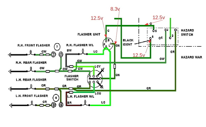
The diagram below is marked for voltages read at the arrow tips with the ignition switch to the “on” position.

Before I get too wrapped around the axle and confused here, is it normal to have the voltage drop seen across the flasher unit? If not, I wonder where to look. May be something is drawing power through the flasher switch?

Thanks for looking!

Edit: Symptoms - 1) L.H. Flasher W/L blinks with turn signal stalk left AND right. 2) R.H. Flasher W/L never blinks 3) None of the actual turn signal lights blink through this circuit and 4) All signal lights blink properly through the hazard circuit.

Very confusing.

So have you tried removing the hazard flasher to see if the normal flashers work or the problems change?

Dear Craig,

It’s perfectly logical.

Firstly, it works on the hazard setting because that is a separate circuit - which obviously proves that the GR and GW circuits work on that side of the flasher switch. If the dash indicators also light up, then those parts of the flasher switch also work, presumably and you can work out how they are connected by measuring which side of the dash bulbs see 12v and which side sees ground…

Clearly the standard flashing circuit doesn’t work. The likely reason is that only 8.3v is being used to power the 12v bulbs and they want their extra missing 3.7v to work! (Caveat:- As the flasher unit is probably an old bimetallic strip which flicks on and off alternately put a LED test light onto the disconnected GN wire - if it strobes 2/3on 1/3 off, then that is where your 8.3v comes from - I am expecting it to do nothing.)

To find out where the problem is, disconnect the GN wire at the flasher switch end and remeasure your voltages. If you have 8.3v on that wire still and it doesn’t strobe an LED, then the problem is at the flasher unit. If you have 12.5v on the GN wire then the problem is after the flasher unit and the next thing to check is the flasher switch.

Use the same troubleshooting technique on that.

Reconnect the GN wire but disconnect LGY,LGU, GR,GW and earth connections from the flasher switch and remeasure your voltage on the GN wire. Reconnect one by one and look to see when your voltage drops.

It does rather look as though your flasher switch is faulty - you already know that it doesn’t connect the right inputs and outputs properly.

You could have also verified that the outputs are not at fault by jumpering a 12v feed to GW or GR directly, although that is a foregone conclusion, since the hazard signals work.

To verify that the main part of the flasher switch is not at fault, disconnect the three flasher unit connections and also LGU and LGY at the flasher switch. Jumper G to GN of the flasher unit and operate the switch. That’ll tell you whether the two main parts of the flasher switch work

kind regards
Marek

Craig,

didnt you mention that you have a mix of standard and LED signal bulbs? if so that can create problems with old bi-metalic flasher units. just a thought

Bob F

Two other things spring to mind. To make the bimetallic strip heat up and cool down (and thus cause the flashing connection to connect), it has to consume enough current to heat up. With an LED circuit, the current usage is lower. To eliminate that from any analysis, just jumper GR and GW temporarily or add an extra 22W bulb back in in place of the LEDs so that current usage is back to normal levels.

If P is for “pilot bulb”, then you’d expect 12v to appear on there aswell as on the GN wire when it is flashing.

That also means that the flasher switch connects GN to either GW or GR and earths the LGY or LGU wires during normal flashing, otherwise there is no point in the double earth connection shown on the flasher switch.

It also begs the question as to how it works the hazard dash indicators - it implies that GW is normally connected to LGY and GR is connected to LGU and that the hazard dash bulbs connect to earth through the flasher unit when hazard flashing. How weird.

kind regards
Marek

Yes, I’m just getting around to reading this so I went back to the shop and tried this…same result with or without hazard flasher.

Thank you for the detailed analysis Marek.

A quick update for today. Although I still have issue(s) with the turn signals I did expose a second problem, that is now rectified, and has changed the picture slightly. As a result of some friendly help offline, I started to focus on the flasher switch. Before I actually removed the switch I disconnected all wires leading to the switch pigtail. This left a 5-way connector dangling from the end of the switch pigtail. With the switch in the neutral position I was looking for no continuity to the switch grounds or from one color wire to another.

What I found was “leakage” within the 5-way. I measured 830 ohms UY to LGY; 540 ohms UY to LGN; 740 ohms UY to LGU. UY appeared to be the problem. I pulled UY from the 5-way and had no continuity between it and the other wires. I then removed the 5-way and connected everything back up with single connectors. I now measure voltage in accordance with this updated diagram: (Note- ignition switch on and turn signal switch center position)


I think progress has been made by eliminating that voltage drop that showed up on the GN wire. But not only do I still have another issue I might have two! For example, why is there battery voltage on the LG wires? Is the flasher switch bad? The flasher unit? Or both?

Tomorrow I will continue checking and I will also run through Marek’s instructions.

Thanks all!

Dear Craig,

You haven’t given us the right information before and have been slightly naughty with your “upgrades” - you didn’t say you had LEDs in the warning light holders or that the new flasher was a different type to the other one - this may or may not be relevant.

Remove ALL of the connections from the flasher switch and diagnose what it does when it connects left or right.

The two flasher units are supposedly identical in operation so you ought to be able to swap them over. to help with diagnosing what does and what doesn’t work, especially since you know that the hazard flasher already works.

I would connect the hazard flasher into ordinary flasher position and put ordinary bulbs into the warning lights. Then I’d see what does and doesn’t work when I try to use the indicators in normal use.

Next, to aid my understanding, I’d like to known whether the flasher warning lights are normally supposed to light up when the hazards are being used.

I would then disconnect the flasher switch completely and work out what it does when it is operated and when it is not being used. My guess is that it is supposed to make a connection form LGY (or LGU) to earth AND from GN to GW (or GR) when it moved to the right (left). I am also expecting it to connect GW to LGY and GR to LGU when not being used.

Next - your flasher units. According to the Jaguar diagram, both units appear to be the same, save for maybe their current rating. According to your circuit, one of them is for LEDs, but the other is standard. What you have to appreciate is that LEDs are diodes and conduct in one direction only, but the circuit looks like it wants to light the warning lights with 12v from the flasher unit (earthed at the flasher switch) in normal operation OR light the warning lights with 12v from the GR and GW wires via the hazard switch and LGY/LGU wires and earth them at the flasher unit in hazard operation. Only a normal bulb (or a bidirectional LED) can do this and it is expecting to alternately ground the P terminal of the flasher unit, assuming that the warning lights are supposed to be active when hazards operate. If that is the case, then you’ll have to replace the two warning light bulbs back to ordinary bulbs to make it work.

However, if the warning lights were never intended to light up when using the hazards, I’d expect the flasher switch to not have any connection between GW and LGY or GR to LGU when not in use and that LED bulbs in the warning lights would be fine so long as they are in the right way.

Lastly, why do I have battery voltage on the LG wires? You have battery voltage on the LG wires because they are connected to 12v. You can think of voltages as being like a canal - they are always at the level of the canal, no matter what. When a lock gate is opened, the level of the canal at either side of the gate now equalises to either the higher or lower level, depending on what side of the light/motor/relay they are sitting relative to the two battery terminals. The level of the water drops where the work is being done - on either side of the light/motor/relay winding, but is constant and either 12v or 0v either side of it, depending on the connection. This means that anything that is connected to the battery stays at 12v forever until a circuit is made via a connection to the battery 0v terminal, at which point you’ll see 12v everywhere before where the work is done and 0v after where the work is done.

kind regards
Marek

EDIT:- you appear to be saying that the headlight high beam flasher (the UY wire - previously unmentioned) appears to interfere with the turn/indicator operation (also unhelpfully called “flasher”). You need to clean the indicator stalk inside where the connections are made by the sound of things.
1 Like

Craig,
As I understand the circuit, having 12v on the LG wires with ignition on and indicator stalk centered is correct. The flasher switch provides the ground to the appropriate warning light when it is placed in the L or R position. The diagrammatic representation of the flasher switch is somewhat confusing, but is intended to show that, for example, when in the Turn R position, the switch contact is “up”, and (a) connects the GN from the flasher unit to the GW wire, and (b) shorts the LGY wire from the RH flasher warning light, to the adjacent ground. So, the RH flashers come ON, as does the RH Flasher warning light. The current through the RH flashers causes the bimetallic strip in the flasher unit to heat up, and disconnect the power from both the L and P terminals of the unit, so the flashers and warning lamp are extinguished. The bimetallic strip cools, returning to its original position, and re-makes its contacts to provide 12v to L&P, restarting the cycle.I hope this makes sense…

-David

Testing of the switch revealed issues. So it’s out! Now, if I separate the switch at the contacts by removing these two screws, how many pieces ( rounded to the closest 100) will fling apart?

Looks pretty gunky to me:

From memory, 3 bits.

For stuff like this it helps to put the piece, and a small screwdriver inside a large ziplock bag. It also helps to flick the “high speed” switch on your eyes before you release the final screw.

1 Like

There are pictures in the old photo albums if you search for “turn signal” when in the photo album section of the old website

You will soon determine where it does and where it doesn’t connect when the switch goes left or right, so the big leap forward is at hand. It may be that the pigtail has a duff connection or that it is no longer well soldered or it is mechanically broken. Hopefully it is just very dirty.

kind regards
Marek

Well, well. This has been very enlightening. The switch is not designed in any way that I thought, even though I didn’t know what to think. Later, I will try to construct some kind of diagram of how it actually works but for now I just want to get down what’s, for the moment, in my head.

There are two grounds in the pigtail. One of them is strictly for the horn. My horn is in the stalk. The second ground is for some of the lights in the circuit but not all. Here it goes:

There are two rows of three buttons that represent the six wires that operate the lights in this circuit.
Top row =…GR…GN…GW
Bottom row =…LGU…B…LGY
As the stalk sits in the center position, a “bar” sits centered on the GN and B contacts. This bar is wide enough to bridge two contacts but not wide enough to do so from the centered position.

Selecting a left turn signal bridges the GN / GR wires on the top row and the B / LGU wires on the bottom row. LGU is getting its power from the “P” terminal on the flasher unit and grounding through the B wire. GR is getting its power from the GN wire via the “L” terminal on the flasher unit and grounding through lights, front and rear left side.

Selecting a right turn signal bridges the GN / GW wires on the top row and the B / LGY wires on the bottom row. LGY is getting its power from the “P” terminal on the flasher unit and grounding through the B wire. GW is getting its power from the GN wire via the “L” terminal on the flasher unit and grounding through lights, front and rear right side.

Ok, it’s down. I will try a diagram later. The good news is after cleaning up the contacts I have less that 1 ohm across any intended connections and no continuity across any unintended connections. Now if I can just get it back on the column.

Once you get it worked out and operational Craig, maybe you should do a
how-to guide in taking apart the turn switch, testing, repairing and
putting back together?

What you are saying is that the top row provides normal 12v to either of the turn indicators from a flashing GN wire from L on the flasher unit but the bottom row is the final connection to earth of the warning light flashing LG wire from L on the flasher unit.

In your case, because you are using aftermarket LED warning lamps which are voltage directional, you must make sure that the LG/BW and LG/BR connections are the right way round for the bulbs being used otherwise the warning lights will not light when you indicate.

It also means that the warning lights are not expected to flash when using the hazard.

If you want them to flash when the hazards are on, you can do that by disconnecting the LG wire from the new flasher, disconnecting the BW from the LGY and finally disconnecting the BR from the LGU. Reconnect LG to earth and the BR to GR and the BW to GW and reverse the polarity of the warning bulbs (because LEDs are voltage directional LEDs and you’ve just swapped the direction of 12v to ground).

Having a near-zero resistance at the contacts of the flasher switch means your indicators will actually light up this time. Ascertain also that the headlight flasher doesn’t affect the indicator flasher function and then I think you are done.

kind regards
Marek

Hi Marek,
The normal turn signal indicator lights do not operate in Hazard mode, only
the central hazard warning light operates. You can tell that from the way
the system is wored.

Now this is for my '68 S1.5, might be the same for other cars, might not.

It wasn’t obvious to me at the start of this at all. The alternative was that the flasher switch might have been wired internally to power the warning lights from the GW and GR wires coming from the hazard when set to the neutral position and which could have got earthed through the flasher can.

The s3 simply connects the warning lights up together with their respective indicators. This means that the hazard flasher powers everything when the hazards are on. It also means you only need a 3way switch rather than a hokey 5way switch to make it all work. I have no idea why they made a complicated and convoluted connection system with wire colour changes just to make the warning lights flash, especially when it won’t then flash them when you operate the hazards.

The problem with these diagnostics is that no one bothers to describe how it works before it is broken. Hopefully this thread now spells that out.

kind regards
Marek

Gentlemen!

I have flashers! Both hazard, with the pilot lamp, and turn signals all around including the flasher W/L!

This is a list of faults that, with your help, have been identified and fixed (I can’t believe it to tell you the truth):

  1. The Hazard Flasher Unit was inop and not putting power out on the “P” terminal therefore the hazard pilot lamp did not work. A NOS flasher unit was sourced and installed.
  2. The turn signals and indicator lights on dash were doing all kinds of crazy things. The first item found defective was the 5way connector that hangs off of the pigtail for the turn signal switch. Voltage was “leaking” from three of the wires joined in there through the UY wire that was also joined there. I removed the 5way and connected all wires via single bullet connectors. This eliminated one of the many faulty indications but still had problems.
  3. Then I went to the switch and started measuring/logging continuity values for every pair of wires with every turn signal switch position. High resistance values prompted me to remove the switch, inspect, clean and replace. Testing the system now resulted in basically the same faults. But the switch is nice and clean!
    4a) In the meantime I had installed a new LED rated flasher unit (the one by your left knee). While trying to sort it all out I took a gamble and bought a second LED rated flasher unit figuring the first one might be defective. The second one did behave differently so I thought I was on to my problem. After cleaning up the switch, neither of the two new LED flasher units worked so I pulled the NOS hazard flasher unit that I put in before and placed that in the turn signal circuit and…EVERYTHING WORKED! Except one last thing.
  4. The right hand flasher W/L (the green one on the dash) didn’t work when indicating a right turn. So I removed the bayonet style LED bulb, flipped it around and viola! I’m 100%

Next time you take a car to the shop with some little electrical gremlin and the labor charge is 100 times the cost of the part to fix it, you’ll know why.

Edit:
4b) I just wanted to add that the issues I had with not one but two LED flasher units failing was most likely caused by the voltage leak in the 5way connector “frying” those flashers. That voltage leak was probably the primary cause of the circuit anomalies.

Excellent description David. I have been so busy working it out that I just noticed you described exactly what I did but in 100 fewer words. Thanks.

Congratulations Craig! Sounds like a nightmare of a journey, and I thought
my Hazard system problems were interesting!