Good stuff, great progress.
I installed Audivox accessories in my 79 IHC Scout. Trip computer and cruise control!! it was fun!!!
Carl
Warning: Sit down - long post!
Wow. It’s hard to believe two months have gone by since my last update!! It feels like I’ve made a lot of progress but when I stop and reflect, it doesn’t seem as significant as it felt. After I got the engine running I uncovered some other issues that needed to be resolved. Note that I have been able to diagnose and figure many of these things out through the great sources of information on this forum - I have barely used any of my manuals at all (yet). I thank you all for that!!
First off, the 3-wire 10SI alternator that was installed was overcharging the system - at one point I’d measured 16.4v at the battery, and 15.5v at the ignition coil. I disassembled the 10SI, and while I could have rebuilt it, I chose to install a 3-wire 12SI for better cooling, easier workload on me, and not much more money (if any at all). I didn’t really need the 12SI higher amperage output (78 amps), but I sized the wiring to accommodate it.
As as example of the 10SI internal condition, here’s the diode trio I removed! 

Here’s the 12SI installed:

While I was at it, I also removed/replaced some “extra” wiring that was no longer needed, and removed the generic ammeter so I can install my new voltmeter (maybe this weekend). It took me a while to trace all the wires connected to the aftermarket ignition “relay” that was installed in the stock location near the battery, and to also figure out how it was “supposed” to work. It turns out that the “relay” function was not working (bad internal ground connection) and it was mainly functioning as a terminal junction block. Figuring all of that out took me quite a while with my multimeter.
Wiring I removed:

Ignition “relay” external

Ignition “relay” internal

Generic ammeter, and new Smiths voltmeter

I also concluded that the wrong ignition coil was installed. It was measuring 1.6 ohms and considering that I don’t have a ballast resistor, it should have been 3 ohms. Combine that with the over-voltage from the bad alternator, I was really pushing some current through the coil!! I am surprised the Allison XR700 (installed in 1987) is still alive!! I installed a Petronix FlameThrower 3-ohm coil, new NGK BP6ES/7333 spark plugs, Magnecor 7mm ignition wires, rotor, and a new push-on style distributor cap. I also removed and cleaned all the fuse blocks behind the dash, and reinstalled with all new fuses and a little dielectric grease.
After all of this, I synced the carbs with my new EMPI carb sync tool. I’m not sure if the reading at idle means anything, but with the carbs synced and the engine idling at 750-ish RPM, the gauge was reading ~11.5 kg/hr for each carb. I had ZERO luck tuning the single carb throttle bypass valve (even though I rebuilt it), so i just screwed it completely closed for now.
I completed flushing the coolant system with several cycles of Blue Devil radiator flush and clean water, and luckily the internals seemed fairly clean. The system is now topped off with 50-50 coolant and distilled water.
I’d noticed my tachometer was reading high as compared to my multimeter inductive- pickup RPM reading, so I removed the tach to access the calibration adjustment. Using info from the archives, I drilled a hole in the rear housing to allow me to adjust the tach with it installed in the car. It’s now accurate at idle and “close enough” up to 2500 rpm or so. I’ll verify things again once I get the car on the road, which is still quite some time away.
Calibration hole, drilled and plugged in the rear housing of the tachometer:

Next up - brakes. I have ZERO brakes, and I can tell this job is going to take some work. First step I took was to remove the two brake reservoirs, which I did yesterday evening. Neither are in great shape, but amazingly the switches still work! Here’s a picture of the worse of the two:

Sorry for the lengthy post, but thanks for reading, and THANK YOU for all the informative posts that keep me moving forward!!
RobY
4 Likes
Rob, great work. In the Fla. heat too!
Great to read of your progress. And the photos are appreciated.
You will have a great sense of satisfaction as you get each item properly fixed!
The cork float in the reservoir should likely be tossed out as it is likely waterlogged with brake fluid and no longer floating. And even if it is floating, it will soon be disintegrating into pieces. Some people replace it with a synthetic cork. Others buy a new float/cap assembly which has a metal float
Dennis 69 OTS
Hi Rob,
Your off to a great start, I’m impressed!
Cheers,
LLynn
You’ve been busy! It might inspire me to get off my lazy butt and do something.
Nah…
1 Like
Ditto! Wish I didn’t have so many non-Jag projects.
1 Like
Rob,
My original brake fluid reservoir caps looked just like these! It’s amazing how these aluminum caps just fall to pieces over time.
Yeah, they were so bad I couldn’t unscrew them. I used some needlenose pliers and peeled them off!
Is the stake down kit a common upgrade? In my limited time I haven’t heard anyone else mention it for the E’s. Googling it shows it mentioned often regarding XJ6 engines.
Very common. Do both the intake and exhaust. Cheap insurance. The XJ6 uses the same basic engine as the E-type.
The stake down kits came into vogue (AFAIK) with the XJ6 due to British Leyland changing the Aluminium used in the heads. They are not normally required on the earlier heads but as stated its cheap insurance if you have any doubt as to the integrity of your head.
I got the master cylinder, slave cylinder and booster assembly removed today. As you can see from the pictures, I found all the brake fluid that was missing from the reservoirs!! That pan is ~ 1.25” deep with fluid.
I am convinced the telescoping steering wheel is to better enable you to get your upper body deep in the driver’s footwell! 


RobY
Time for a total brake rebuild. Oh yeah.
1 Like
Hi Rob,I usualy take my steering wheel off and seat out when working in the foot well! Getting to be an old fart now so need to make these jobs as easy as possible.
Regards Gerry 62 Ots.Ontario Canada.
I was able to remove the clutch master cylinder without too much fanfare. Nasty!

I was also able to remove the clutch slave cylinder. That effort took a little more creativity and coaxing language, but I was able to get it out. With all of the various factory clutch slave configurations that were offered, I’m pretty sure I have a variant of a non-hydrostatic slave (slave is 3" long) with a hardware store external spring and homemade spring mount approach. Shown here:

The rod adjuster assembly was completely seized. I’ve soaked it in PB Blaster and broke it free with a little leverage from a wrench. It’s now able to rotate about the pivot pin, but I’m not yet able to remove the pivot pin to enable removal of the adjuster and rod. The pivot pin was secured with a hitch pin at the bottom. With the hitch pin removed, the pivot pin should ideally just push straight up and out of the adjuster assembly, correct? Here are a couple of views of where I currently am -


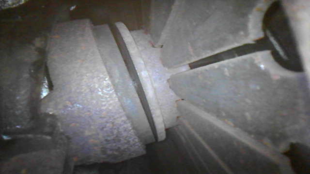
While I was down there I inspected my throwout bearing for wear, through the bell housing inspection hole. From the notes I have, it was replaced about 32K miles ago…circa 1984. Looks like there’s some good meat left to it -
RobY
That is my recollection. If you can get something in the small hole and rotate it perhaps that will help.
The pin on mine was secured with a funny clip but that may be a later configuration. I also have the spring and such on the opposite side but again, no guarantee that is correct (though it is easy to get at).

Unfortunately, my pin doesn’t have a hole in it either - it’s built for the special clip that yours uses.
I tried make a press with a c-clamp and a socket (one that would encompass the top of the pin and allow it to move upwards with pressure applied to the top of the socket and the bottom of the pin). I was able to get some good pressure on it, but it didn’t budge.
I hit it more with a wire brush and PB Blaster and I’ll let it soak overnight. Tomorrow I may hit it with some heat and see if that allows some progress. I would have done that tonight, but my wife’s out to dinner and she hid her small kitchen torch from me!
Thanks!
RobY
To me, it’s tough to beat the feeling you get when your plan for a problem actually works!
C-clamp socket press:

Same as above, with a smaller socket added to the bottom, after the pin had been pressed flush with the bottom flange:

Got that sucker!

Geo, looks like I was wrong. Even though the pin was grooved for a retaining clip or hitch pin, it also has a hole (see the last pic). I just couldn’t see it when it was installed. I don’t think I could’ve gotten enough leverage with the hole anyway - the pin was in there TIGHT.
RobY
1 Like