Given the critical function of the hubs (lose a wheel at 70- not pretty…) I’d replace at least the welded unit and I’d take a really close look at the driver’s side for worn splines etc. They really aren’t very expensive and are readily available from the usuals. Part number C19225.
Thanks for the feedback fellas. I’ve added a replacement to my purchase list!
RobY
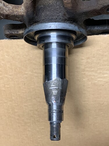
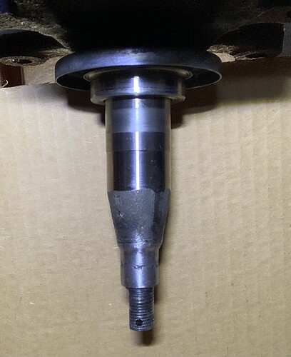
…and I guess I’ll be adding a front stub axle shaft to that list as well. The end is gouged really good and I can see the inner race of the outer bearing has some wear.
I think I’ve read elsewhere that removing the inboard nut won’t free the shaft, and I’ll need a hefty press, to press the shaft out of the carrier?
Stub shaft pics -
From the top:
From the bottom:
Correct and heat will help, there have been instances where it has popped out easily, both of mine came out with a bang. When you get the replacements just do a trial fit of the inner bearings before you fit them to the upright, my bearings slide straight through both sets of stub axles I received.
I have a video but its on my iPad and it wont allow me to upload it and I can’t see a way to send it to YT either.
Thanks Robin. From the JL reading I’ve done, the bearings should slide as you described. Is that what you’re saying - to verify that they do so on the new shaft, before installing it to the upright?
Not the amount of clearance these bearings have, because they are set up with end float the bearings can, and do, spin on the shaft hence the wear pattern you are seeing, I ended up using some shaft fit loctite on the inner bearings to try to eliminate the chance of doing that. The only other way is to have a sleeve made that sets the inner and outer bearing races the correct distance apart.
I ended up purchasing the Harbor Freight ball joint separator that’s mentioned all over the archives. The upper ball joint and tie rod end came apart with little effort. The lower ball joint, on the other hand, was a bit of a bear. With the HF tool, and some banging, and some heat, the lower joint finally let go with a hearty POP.
After reading folks’ struggles with removing the axle stub, I was preparing to make a trip to a friend’s shop to use his press. Luckily an overnight soak in PB Blaster, a little heat, and three good whacks with my 4# mini sledge, and it dropped out!
RobY
Before I go breaking anything - just wanting to make sure I’m properly understanding the upper wishbone ball joint assembly. My plan is to disassemble, inspect, and rebuild if necessary.
The ball joint has been separated from the now-removed stub axle carrier and the wishbone is still installed on the car (I wasn’t planning to remove it). The upper ball joint snap ring, top cover, shims, and spring have all been removed. The manual says the next step is to “gently ease out socket 5 and ballpin 6”. Well, of course, this one seems to be stuck in there pretty good. The ball rotates freely in the socket, but neither of them wish to leave the wishbone.
Before I go pressing or banging on things, I just wanna make sure the socket and ballpin are supposed to come up through the top of the wishbone, and the socket isn’t threaded into the wishbone or anything? In other words, I should be able to press on the threaded rod of the ballpin, which is protruding from the bottom, and force it up through the wishbone.
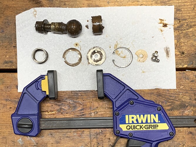
Here’s what I’m looking at, from the top. The fluid is PB Blaster:
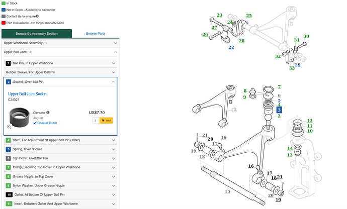
The exploded parts diagrams, parts manual or at SNG, can be very helpful:
“While you’re at” it and if needed, you might as well remove the upper wishbone (keeping track of the camber shims) and renew the bushes on the fulcrum shaft (#18). Lower too.
Thanks Craig. I’ve been referencing that diagram and other that I have. They all seem to show the socket and ballpin drops in from the top - I was just looking for some reassurance that I wasn’t missing something or had it wrong!
Appreciate the heads-up on the camber shims and bushes!
RobY
Looking at the photo I don’t see the circlip. Did you remove that or wasn’t there one there?
Terminology, I think. “snap ring” = “circlip”
Hoping to make my way out to the garage shortly and see if I can pop things out with a c-clamp and socket.
RobY
I have several boxes of Jag stuff that my dad left for me. Some used, some new, some I don’t even know what it is yet. 
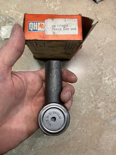
In one of the boxes was a new Quinton Hazell tie rod end and two lower ball joint rebuild kits. I know folks swear by the newer sealed lower ball joints, and that makes sense. However, I’ll probably use these, since I have them in-hand and they’re already paid for. I believe they are correct for a ‘68 E-type (p/n QSJ221RK).
But, for the tie rod end, I don’t think it’s correct based on what I’ve read on JL. The angle is too narrow (~115°). My question is, does anyone know what car it’s for? p/n is QR1178RH:
If it’s the same but doesn’t go far enough for your needs, it is for the XJ and probably others. The E Type tie rods have more travel and work on the others, but not vice versa.
I just received the brand new tie rod end I ordered from Moss (p/n C25447) [EDIT: I actually ordered p/n QR1178S - see follow-up post below]. It has even less articulation - it measures ~110°. I’ll be calling them tomorrow. This seems to have been a “well advertised” issue on JL and UK E-type forums many years ago, and I guess it was never completely corrected.
Looks like SNG may have the properly articulating ones, but are currently back ordered.
RobY
This is sad. The Moss catalog (Spring/Summer 2020 copy I had to hand) specifically highlights the C25447 item “Unlike many reproductions, these ends allow for the original range of motion”. I hope that they just got their inventory mixed up, and shipped you the XJ6 version. Please let us know what you find out, as it will benefit everyone to know if they don’t have the correct ones any more.
I talked with Moss today. The guy I spoke with was very nice and also very helpful.
So, here’s the story:
Despite what I mentioned in my previous post, I had actually ordered p/n QR1178S. This was a single tie rod end (TRE) for a “6 cylinder 61-71 E-type”, for which I ordered two. This approach was cheaper than ordering the pair of TREs they offer under p/n C25447, by about 2.5X.
I received one TRE that was in a box that had the QR1178S number, and also the C25447 number. The other TRE was backordered. In talking with Moss, the QR1178S is a very old part, and has been superseded by C25447. As of now, if you search Moss for QR1178S it won’t even come up anymore. If you Google it, it could come up on the Moss website, but will be shown as “NA”. In other words, I don’t believe anyone else is at risk of ordering the TRE that won’t work, at least from Moss Motors.
The Moss rep was confident the newer, C25447 pair of TREs are the ones I need, and should articulate to the ~125° we 6-cylinder E-types need (reference the note that @davidxk mentions above). So, I ordered the pair of those, with free shipping, and was credited the original charge for the older part that wasn’t a proper fit. My fingers are crossed that the pair I’ve now ordered are correct - I will definitely measure when they are delivered!
RobY
FYI - these arrived in the mail today and a quick check with the protractor verified they are the proper ones.
Rob Y
Just a little update since it’s been a while -
I’m not done with the front end yet, but I’ve made some good progress.
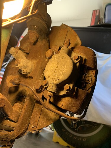
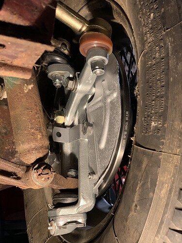
Cleaned and painted the axle carriers, brake calipers, and brake dust shields. Replaced the tie rod ends, upper and lower ball joints, and the stub axles. New brake discs, hub seals and inner and outer bearings and races. Greased everything and set the front wheel hub endplay. I will send the front brake cylinders and pistons to be cleaned, rebuilt and sleeved once I get the rear ones off the car - I’ll send them all at once.
A couple of representative before (RHS) and after (LHS) pictures:
Recently I’ve been working on dropping the IRS so I can get to the rear brakes, and whatever else I discover needs attention. The information found on the list has been invaluable and things have gone smoothly for me. Dropping it really wasn’t too bad. Is installing it harder?
Jack stands placed at the rear of the center body rails. Many will appreciate that I took this opportunity to remove the mud flaps! That’s my sometimes-helper, Trouble, on the left of the picture:
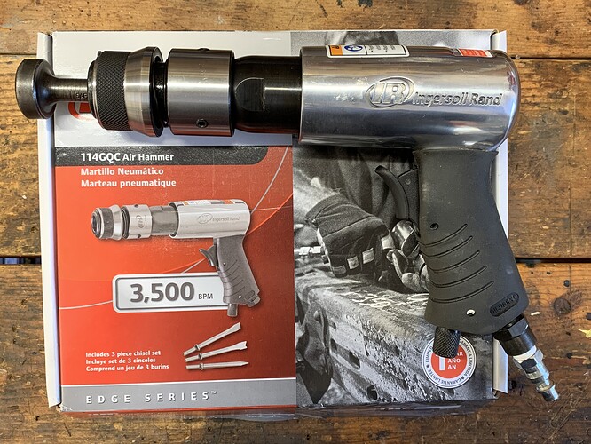
Below is the latest addition to my tool collection. I don’t know how I’ve made it this far in life without one of these things!! This air hammer made quick work of the forward radius arm bushings. A few hits around the perimeter, and then a good shot on the central bolt (reinstalled after removing the safety straps). The LHS dropped free within 30 seconds. The RHS took a little longer - ~45 seconds! I kid you not!! Maybe I got lucky…and that’s ok, I’ll take it!
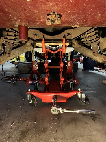
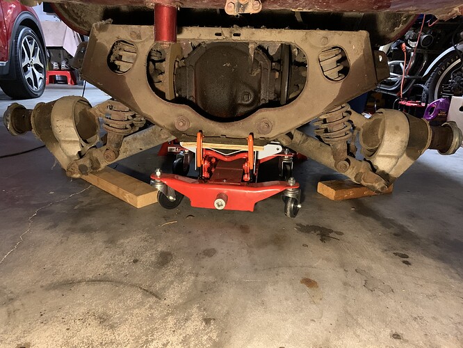
Here’s my HF transmission jack raised into position. I didn’t realize until after-the-fact that I was slightly off center, which caused the left side to be slightly heavier. A little pressure from my hand on the right side hub kept things level.
With the jack stands at ~18” height, I don’t have enough room to come out the back. More than enough room to come out the side though.
Now the “fun” starts!
RobY
