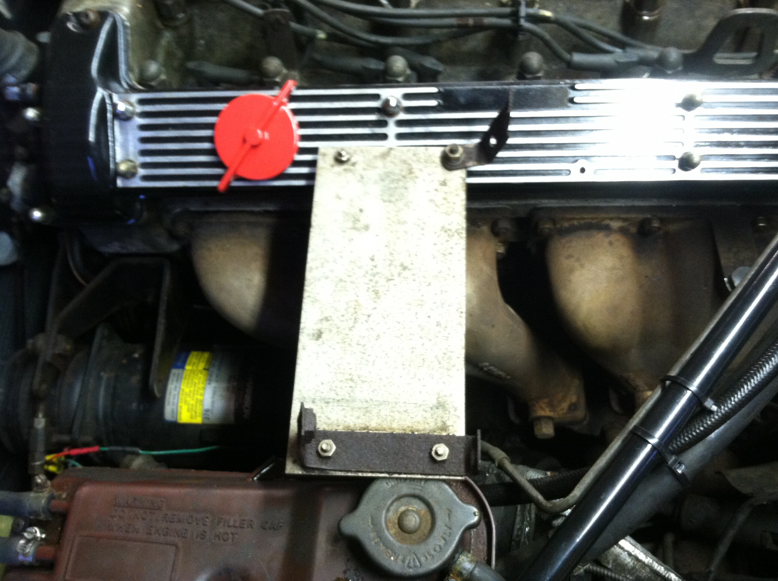
Forgive me,believe it or not, I forgot where this plate goes back on the car. I thought it looked like a heat shield maybe. help Mark

and the A/C is not wired up ,It looks grounded with a green wire but the other wire is not connected anywhere
A/C pump ,I should say
It is a heat shield part C37293 and goes under the front exhaust manifold to shield heat from the alternator or aircon which ever is fitted to your car.
Hey Gary, thanks for the info very much. Now I can figure out how it fastens on in that area.
awesome,thanks,Mark
I don’t know which way you have to turn it but one of them little legs connects to the heatshield for the exhaust. There’s a little hole. Protects the compressor.

The front bracket is attached to the first bolt of the exhaust manifold and the second bracket is attached to the heat shield that goes over the exhaust manifold see small hold in picture attached.
Note my front bracket is attached with out the heat shield.

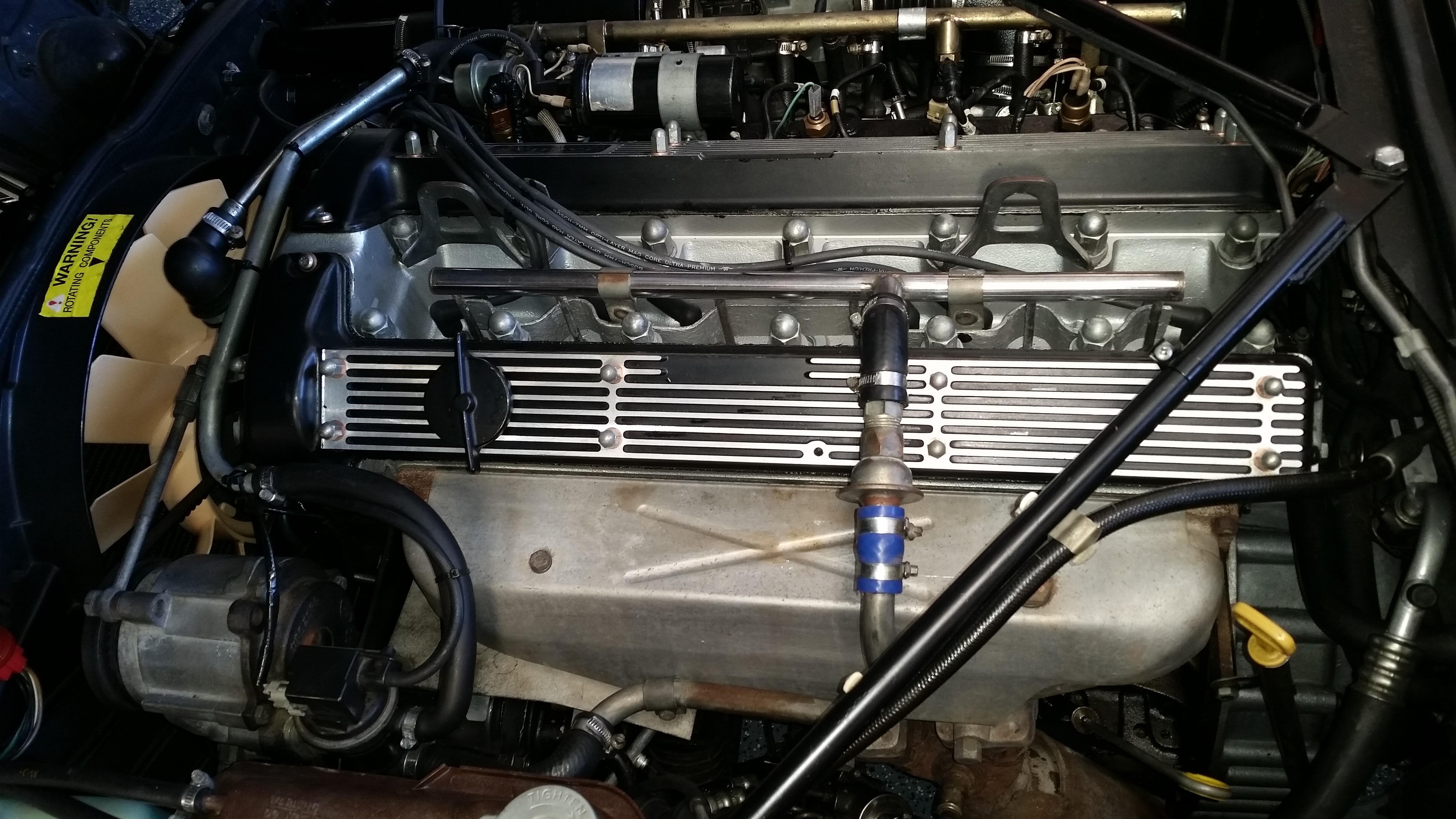
Here’s mine (as it was when I bought it)
Could be that one goes to the exhaust stud, and one to the exhaust shield, and one hangs in the air! Don’t trust the lower left circle. Then it’s like Garys aka what I think is correct.
Mark,
Attached is a picture of that A/C compressor heat shield in my former 1987 XJ6 Vanden Plas that has all of the air injection system components in place. It looks like you have removed a bunch of items from your engine including your air pump, the air rail and plumbing, and the exhaust manifold heat shield which the A/C compressor heat shield bolts to.
Paul
**
Do you plan to get the AC working, Mark…
There are two versions of the compressor set-ups - and some more gen on yours may be required…
Frank
xj6 85 Sov Europe (UK/NZ)
**
Thank you Frank, and everyone helping me. Yes, I would like to get the air compressor wired the correct way, then go from there to
get the AC working . Mark
Unless you have a late '87 model year…VIN after 470xxx or thereabouts…your car was originally configured as follows:
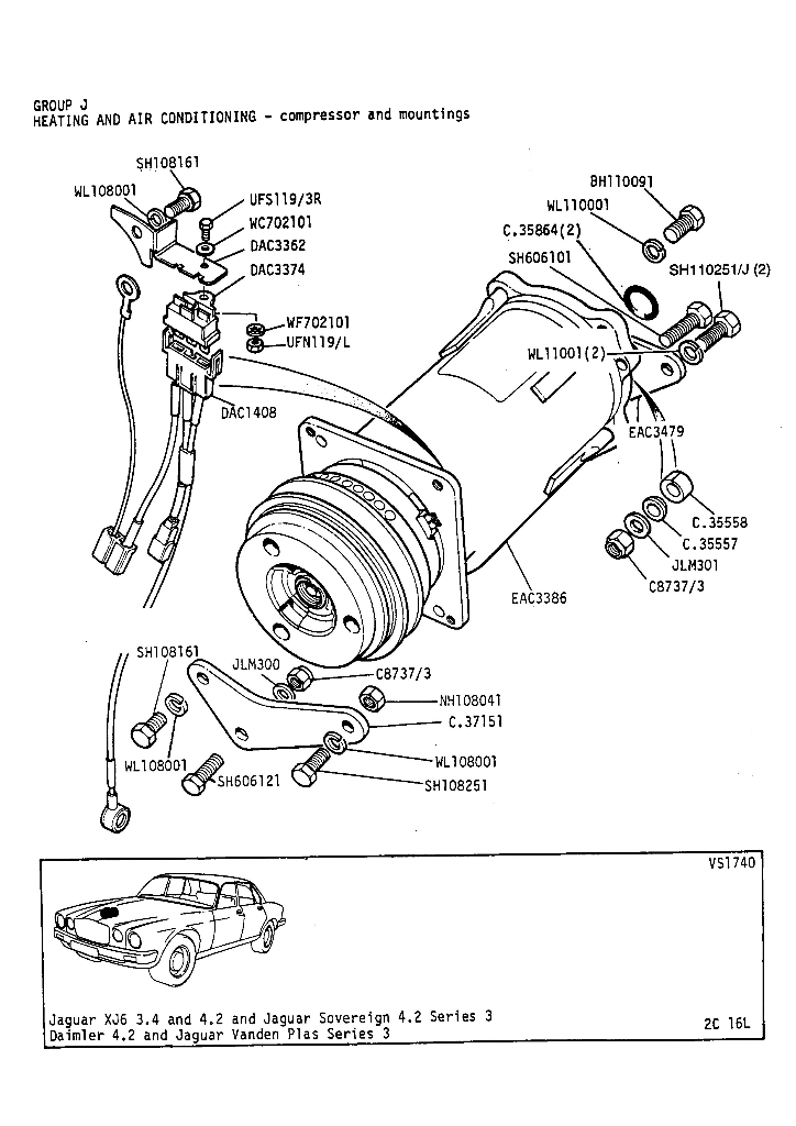
You should have a three terminal thermal limiter fuse attached to the a/c compressor bracket.
Terminal A should be a black wire going to the Superheat switch at the back of the compressor
Terminal B should be a green/brown wire from the controls inside the cabin
Terminal C should be a green wire going to the connector at the compressor clutch
(terminal might be marked “S” on some switches)
This leaves you with a vacant terminal at the connector at the a/c clutch…which should be wired to a good ground.
BUT…
The thermal limiter fuse is often missing and the green/brown wire connected directly to the compressor clutch. The system will work but there’s no protection circuit in place.
Cars after 470xxx or so didn’t have a Superheat switch. Instead they used an HSLP switch—Hide Side Low Pressure. This system did not use the thermal limiter fuse. The green/brown wire gos to the connector at the clutch and another wire (Black? Not sure) goes to the HSLP switch at the back of the compressor.
Some cars have had a Superheat compressor replaced by an HSLP compressor.
The two switches look almost identical but cannot be interchanged. They are different sizes and of course they function differently The only way I kknow of to pistively ID which type of compressor you have is the remove the switch and look at the cavity. The position of the orifice hole tells you which type of compressor you have…although the details of that different in orifice location evades my memory at the moment. Some Googling might reveal it faster than I can remember it
Here’s a pic fo the thermal limiter fuse

Cheers
DD
As Doug says, Mark - it is important to identify your set-up, either by observation or history…
The thermal fuse is normally mounted on the front of the right wing valance, if fitted. You need to identify the green/brown wire which powers the compressor clutch via the Ranco switch through the thermal fuse - if fitted/used. The green/brown wire is powered whenever the function control is out of ‘off’ - check. A green wire then connects the clutch to the thermal fuse - if the thermal switch is working; it should be powered as with the green/brown. And a black wire (clutch ground) is connected to the superheat switch at the rear of the compressor…
If the later system is fitted; the green/brown is connected directly to the clutch - and clutch ground, black wire, is connected to the high/low pressure switch. In this system; with wrong pressure the ground(!) is broken - disengaging the clutch. In the early system; high compressor temp blows the thermal fuse, cutting power(!) to the clutch - disengaging it. A blown thermal fuse must be replaced - the later pressure switch resets when pressure is correct…
Frank
xj6 85 Sov Europe (UK/NZ)
**
**
Have to correct myself here - the hands were faster than the eye…![]()
The black wire on the thermal fuse is thermal fuse ground going to the superheat switch. With excessive temp the superheat switch grounds the thermal fuse and blows it cutting power to the clutch. Clutch is permanently grounded - black wire from clutch…
Frank
xj6 85 Sov Europe (UK/NZ)
**