Good comment all. It seems likely that the IRS/body bracket shims are for the purpose of centering or perhaps for adjusting for an off-center frame member.
David, I look at your pics every day. Your plumb bob on a stick is pretty slick. Your pic:

Good comment all. It seems likely that the IRS/body bracket shims are for the purpose of centering or perhaps for adjusting for an off-center frame member.
David, I look at your pics every day. Your plumb bob on a stick is pretty slick. Your pic:
I’ve also set it as you describe - off the car. It works although you tend to get more negative camber when the car is finally resting on the ground as the weight takes up any slack in the assembly. Also if your car leans to one side it will affect it. It’s good enough however.
On every Jaguar I’ve disassembled there is one shim each corner of the mount inside and out.(4 shims per mount). If you match up the mount to the frame in the car you will see that the mounts are slightly wider than the frame, and that’s what I believe the shims are there for.
That’s why dad had made special knockoffs with flat, steel circles on them to attach a magnetic camber gauge.
I still have a set for the 42 mm Rudge-Whitworth hubs (MGs, Triumphs), if anybody wants them
If only I had my Triumph or my MGs!
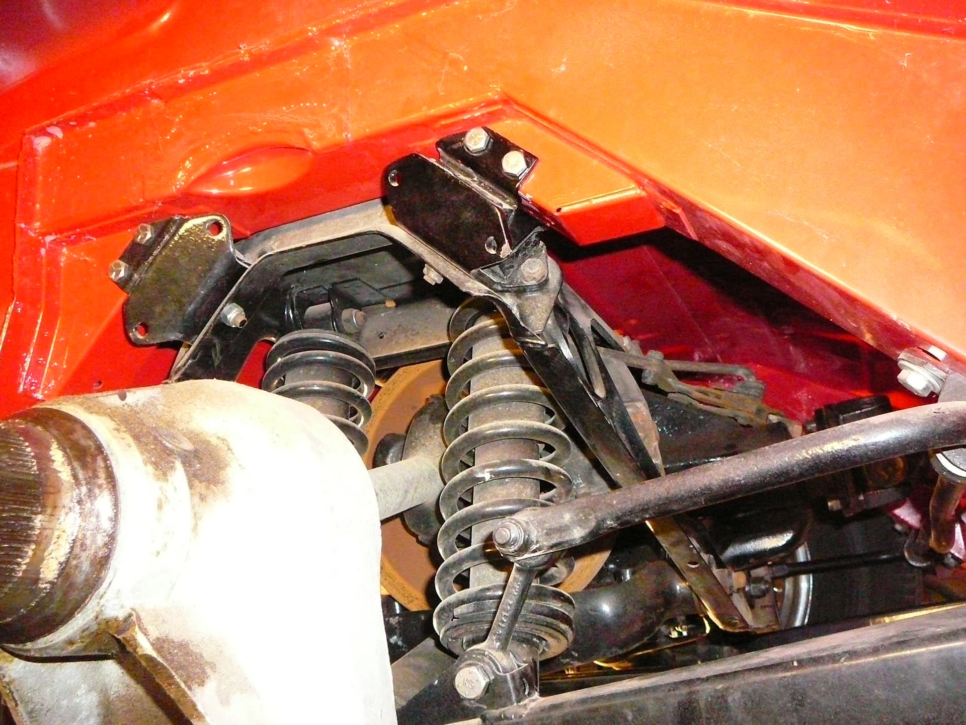
Waiting for parts… Meanwhile fiddling with the IRS-to-Body mounts. My mounts must be somewhat different than others. Mine are Metalastik. The mount brackets fitting over the frame, where the shims should go, are a close fit to the frame. There were no shims when I took this apart. I can get only one shim between the mount flange and the body frame. One shim is a snug squeeze. I’d have to spread the ears in order to put a second shim on the other side of the mount. The ears do not want to spread apart and I’m reluctant to do so. Indeed, the mounts fit well to the frame without any shims.
If I put one shim in place, would it go under the inside or the outside ear? I’ve made this observation with both of the rear mounts and they fit identically.
Suggestions and/or comments? The pics are of the RH side of the car, but the LH side fits the same.
The following quote is from @abowie and it seems to me he is indicating the IRS Body mounts receive a single shim each on their inner side. Or the quote may mean one shim on each side of the mount between the mount and the box section.
What is the width of the new mounts vs the one you removed?
Marco, I only have the ones that came off the car. Presumably they were replaced in 1990ish, but maybe not - I don’t know the history when a mechanic was hired to restore the car. The mounts appear to be in good shape. So no old versus new. The mounts measure 2-1/2" across the outside of the flanges or ears that straddle the box frame; that’d be the distance between the bolt head and the nut.
Were your body frames sprayed with an underseal before painting? They look ‘bumpy’. That could easily take up the shim space.
Just measured the OEM’s mounts I replaced years ago when I rebuilt my IRS. They measure the same as yours : 2.5” on the outside and 2.25” on the inside.
Maybe what mminnich says about the underseal is something worth looking into.
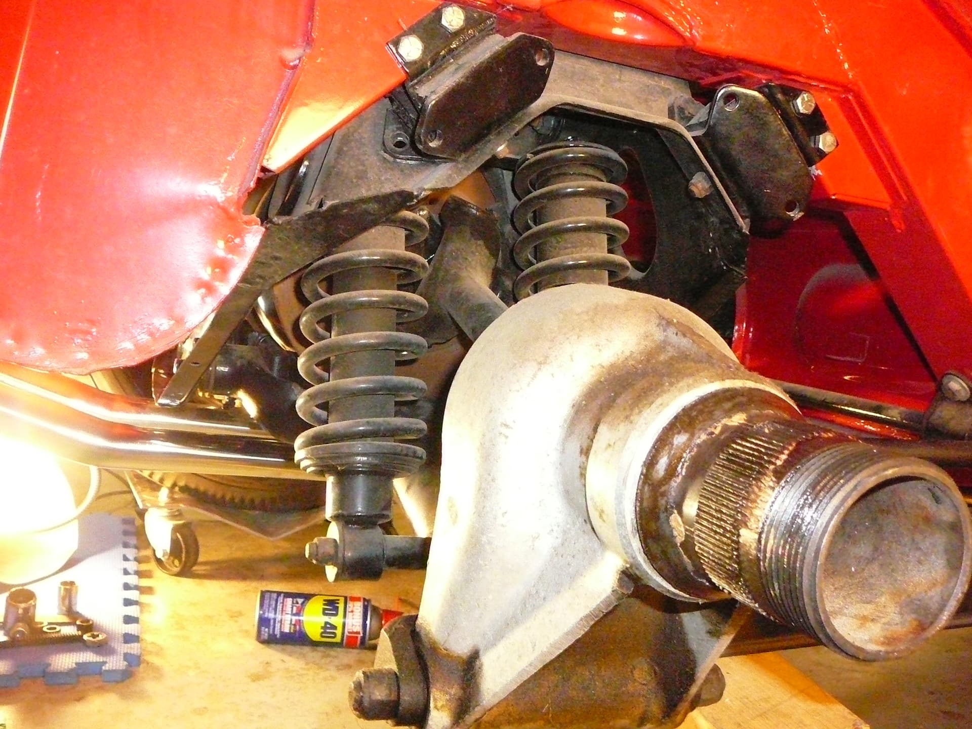
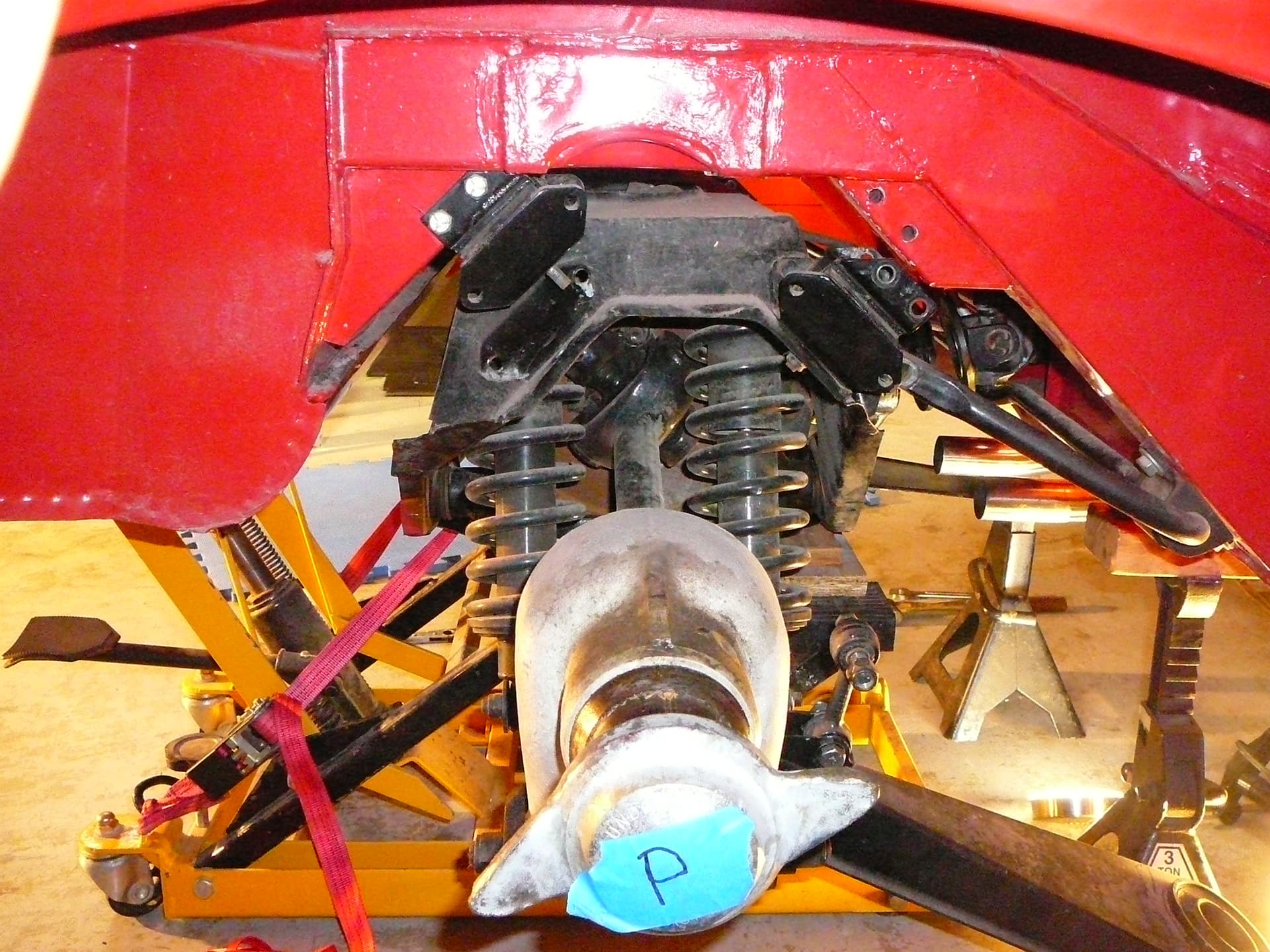
Boy, I’ve always thought the underside of the car is incredibly smooth. The pics below are when I was dropping the IRS. There is only paint and primer and then metal. The car lived its life in Utah and Arizona and then I moved it to Florida before moving here to N. Carolina. It has been inside since 1990 when my aunt bought it and the restoration began. At any rate, there is no undercoating.
I’d like to know what a replacement IRS/Body mount measures. I can spread these on the press, but it almost seems silly to spread them and then shim them to fill the gap I’ve made.
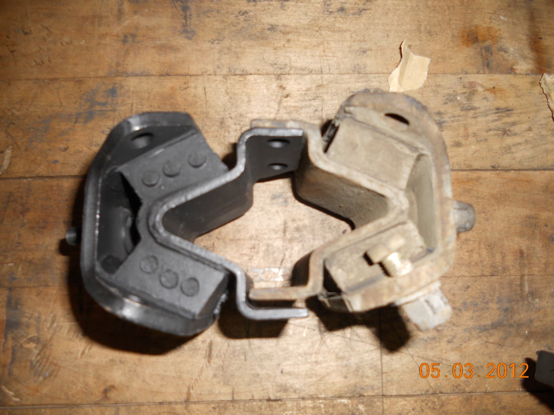
Above your post you’ll see my reply from yesterday showing the OEM mount measurements. Below are photos of the replacements I received compared to the OEM’s. The replacements are wider and taller but when I pointed that out I was told that is the correct replacement.
Thanks Marco. That is kind of you. And helpful! I see the replacement is wider & taller as you say. Just so they’ll find all cases no doubt. I have come to a conclusion though wrt these mounts. After off-line discussion, I think this is the correct policy:
The IRS/Body mounts are to snugly straddle the box beam frame section. The shims are only there to assure there is no gap between the mounts and the box frame section. Use shims as required. If it needs two, then put one on each side. If it just needs one, put that in the inner side of the box section. If it needs no shims, that is also okay. In my case, I’ll put one shim on the inside side of the mount as that is what it takes to make my IRS/Body mount fit snug to the box frame section; the mounts will not fall off under gravity without any bolts if I do this. So the bolts will not “pinch” the mount ears. Good to go!
I’m moving on to the outer fulcrum shafts. I’ve some mangled circular shims there, so I’ll be straightening that out.
Moved on to the half shafts and the outer fulcrum shaft. A couple of interesting finds.
On cleaning and inspecting the Left half shaft that is still fixed to its hub, I found a snap ring was broken. Of course it had to be on the U-joint that was on the hub side.
The U-joints themselves feel good and smooth and about the same amount of firmness. So my plan is to leave them alone. On the one with the broken snap ring, I had a heck of a time getting the one side out of the groove. One needs to recess the bearing cap a bit in my experience. I don’t have a ball joint remover large enough to straddle the errant cross piece, so it was going to be a hammer. I cleaned the area and oiled it and pried out the right side of the snap ring in the pic but that left side was stuck. I finally used a 3/8 Driver and a 3/4" socket and was able to get a few good whacks. So now the snap ring pieces are out.
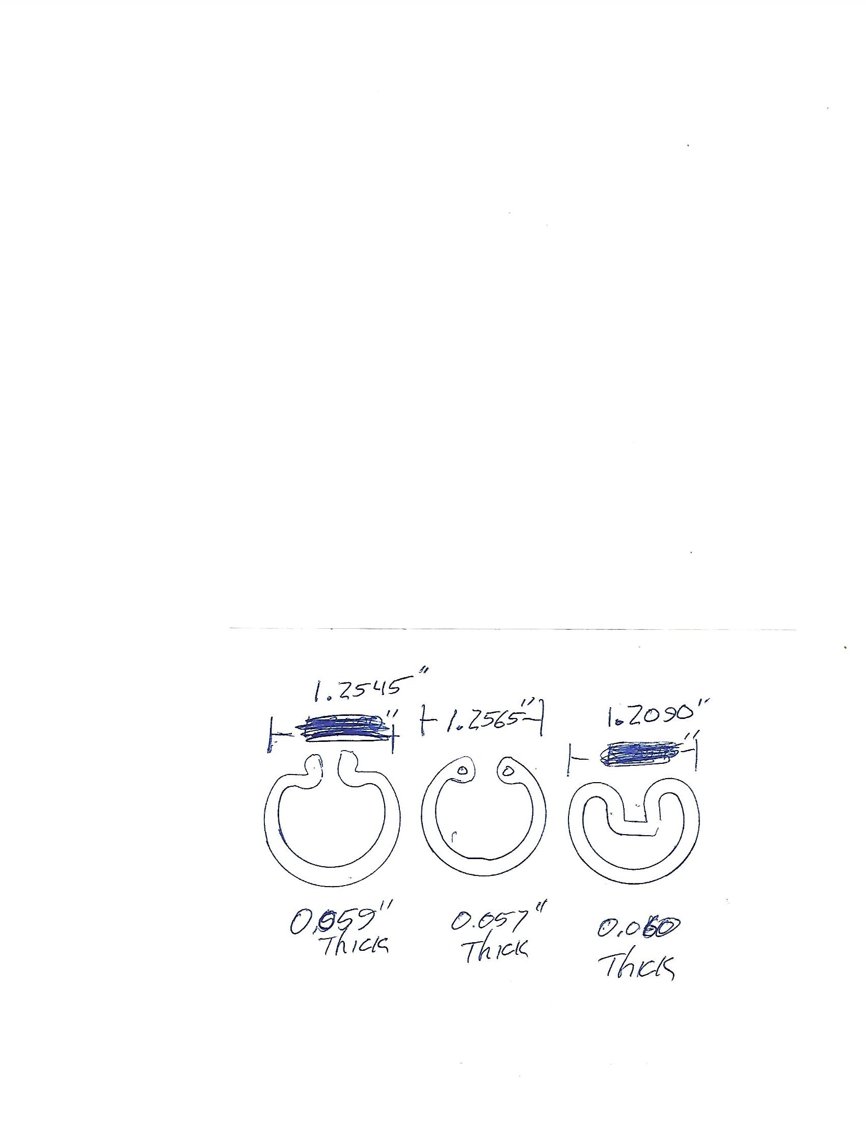
I hope I can find a snap ring for this U-joint. It is a Spicer and the snap ring has that typical Spicer shape to it. It is 0.060" thick and 1.180" in diameter at the inner edge of the groove. I don’t have enough pieces of the snap ring to measure it and I’m reluctant to remove one from the other bearing caps. Also, the U-joint on the other end, that mates to the output shaft, is a different type but has no I.D. I can discern. I’ll call around to local parts houses and Jeep shops and maybe get lucky. I really do not want to pull the splined shaft out of the hub!
Maybe someone has one of these laying around? @Wiggles or @Mike_S anyone?
The next find was more disturbing. The flange on the half shaft on the right side has been cut deeply. Probably a cutoff wheel, but who knows. So I need to either weld this or replace it.
And one more question. On the Outer Fulcrum shaft I ordered new seals and probably should have ordered new bearings. I am told by SNGB that the seal is felt? The one seen in the following pics is rubber I believe. So the question, how best to remove the seal? I don’t have real bearing extractors and usually use a punch from the far side. I could probably use the slide hammer but I thought I’d ask seeing as I’m stuck for the moment.
I’ve got as few of each of these styles laying around. If any of them will work for you let me know and I’ll drop a couple in the mail.
Well I hope all of your got as big a laugh out of this as I did. I never knew this: Only two normal sizes. Big and small. My local parts store had them laying on the floor and just handed one to me with a big grin. ![]()
And thank you anyway John. For all the crap I’ve been faced with on my Jag recently, it is a happy moment to have something easy! Now to just get the cap to go down a bit so it’ll go in the groove.
You are welcome. Glad it turned out the way it did. I don’t need to tell you to make sure there is no debris in the groove; but I guess I just did. ![]()
Does that mean some soon to be less than happy customer walked out of there with a U-joint missing a snap ring? ![]()
Maybe its just me but it doesn’t look like the snap ring is fully seated.
Hello Marco,
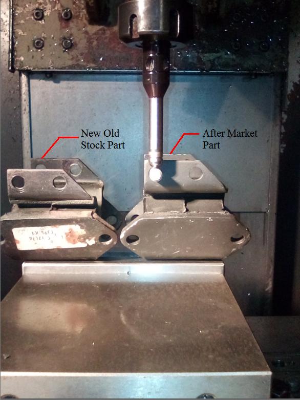
This is another case of the After Market manufacturer punching above their design ability, rather than simply copy what already exists and has worked well in the past.
The following pictures show the typical mounting height difference between a NOS part and an After Market part we had difficulty fitting. The mounting width was also as you have shown.
That extra circa 8mm height difference is significant when mounting the IRS Cross Member due to the angle aspect of the components, but the width difference makes for a really crappy finished assembly with more spacers than would normally be necessary being required. Overall, a really shitty replacement product.
“I was told that is the correct replacement” is the usual acorn that is served up. When dealing with the incorrect handed Window Winder mechanisms for S2 2+2 and all S3 cars being sold, I was told “we’ve never had complaints about that in the past”, notwithstanding that it’s absolutely impossible to assemble the Window Winder mechanism configured as shown in the Parts and Workshop manual if the vibration damper is left in place inside the door.
Regards,
Bill
I just don’t understand the difficulty of coping such a simple and important item. Taking a better look at my top view (posted in my response to Scott) maybe the issue is the rubber is vulcanized in the incorrect position ?
Also, without researching , did Jaguar have a slightly different version of this mount, maybe for a sedan, and the manufacturer was given that version vs an e-type one ?
Trying to understand…….
Marco