It appears the 4 bolts that bolts the differential case ( pumpkin ) into the top of steel IRS cage are missing since that shop assembled it in the 90’s
They were indeed Greg! The entire IRS was shoddily assembled and put into the car back in 1994-95. I didn’t own it then, my aunt did. The car hasn’t been driven since it was put into that shop in 1990. I bought it in 2003 and basically took a year to straighten out the title. Then I did a little work on it - replaced the pipes behind the dash, etc. and set it aside for years. Those 4 bolts I discovered missing when I dropped the IRS a few weeks ago.
Thanks for reply , when I opened your topic I responded to your 1st pictures and later realized I had replied too quick . As I followed what you have been doing ( by going down your postings of work on the IRS ) I see your progressing great and focused on doing it well .
my reply was shown way down after a few comments on those 4 bolts .Take care
thanks for your input; it amazes how the J-L forum works and so many are willing to share their hard-won knowledge.
I’m going to curtail this particular thread soon as it is all about the teardown and is becoming to long to be useful for those seeking information. I’ll start a Scot’s Rear End Part 2 and that will be about the assembly. Probably do that within the next week.
thanks again.
2 Likes
I pulled my brake cylinders apart to inspect them prior to having them re-sleeved. I have 3 Dunlops on my Series 1 car and one Girling. The Girling has a 1-3/4" bore and is a satisfactory replacement for the no longer made Dunlops. However, I want all 4 to match, so I’ve found a rebuildable example.
As these rear brake cylinders have the compensation pins inside the cylinders, I worry about the compensation circuitry inside the pistons being dirty, contaminated, or otherwise dysfunctional and not finding that out until the IRS is back in the car. Here’s a thread to discuss that.
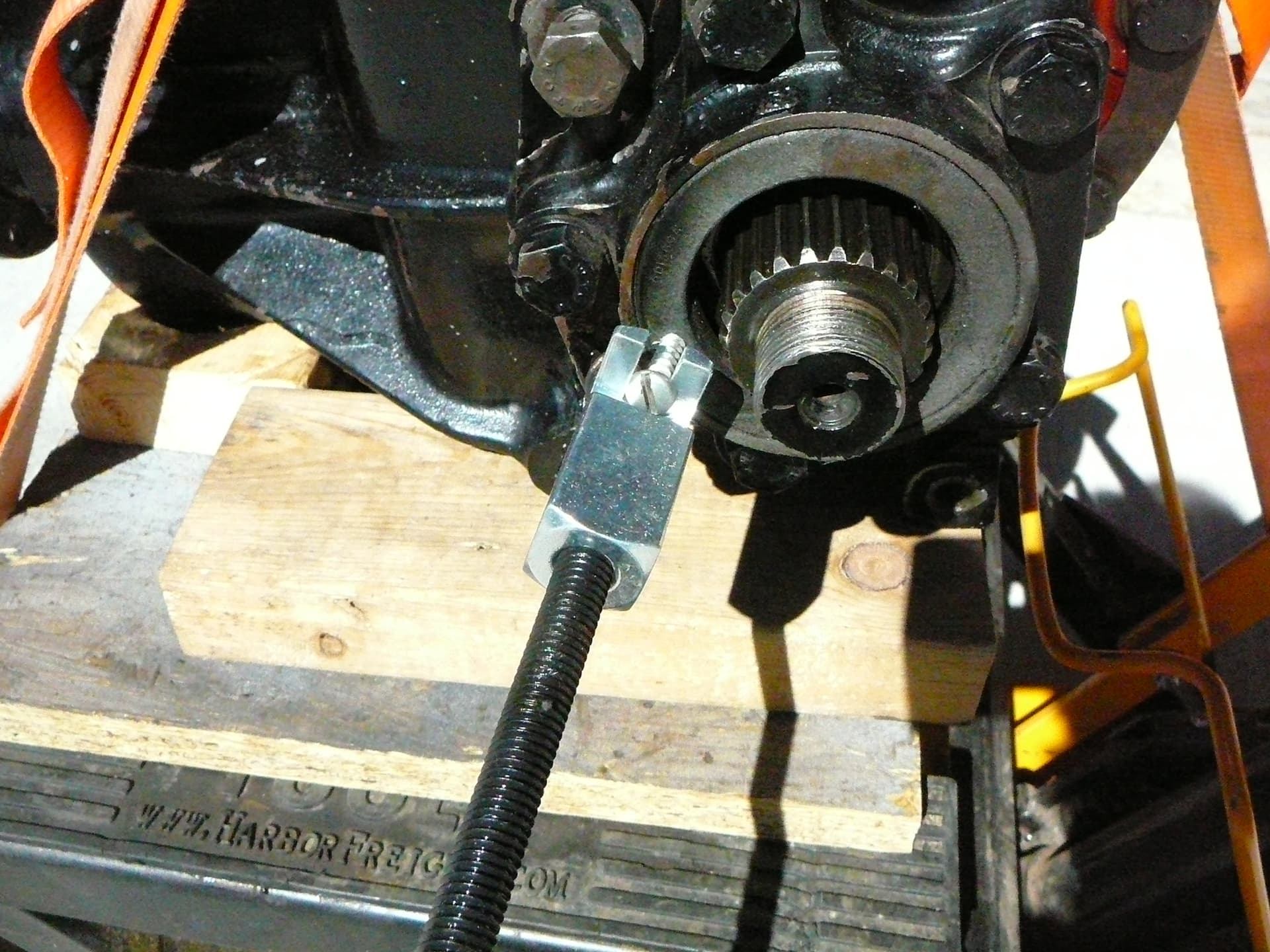
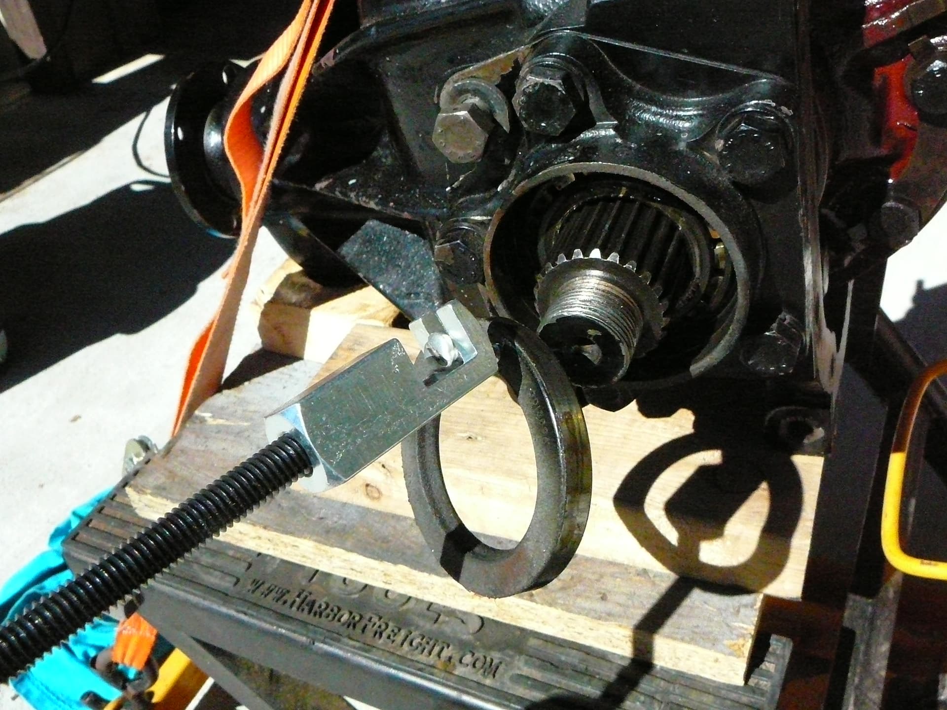
Well Heavens to Betsy, Tony has the right idea. I did what he suggested and got a cheap slide hammer. One that allowed the use of a sheet metal screw. Drilled a hole in the side of the seal…not too deep, and affixed the slide hammer. This was super easy, left no damage and no residue - with the use of a vacuum that is the tube pointing at the drill hole.


My decision on the seals is to replace the two output seals but leave the pinion as is (I can get to it later if necessary). I am so glad I did as while the right side flange’s land for the seal was in nice shape, it was a different story today. Today was the left side removal and that flange had some moisture contamination that caused a bit of pitting on the seal land. I tried to hand polish it to no avail and took it down to the machinist. I thought he might turn it but he thought that’d remove too much material. Instead he mounted it in a lathe and used a rotating wheel with Scotch Brite (80 grit) to polish out the pits. It didn’t take long and he didn’t even charge me! Mic’d them before and after and you couldn’t read the difference. Last pic is both flanges polished and ready to be installed.
Thanks to @Dennismo and @Clive_Wilkinson and others for the idea to have them polished.


And the pair after polishing.

One last thing to mention. On the other thread about the calipers, I have finished up with that and the cylinders are off to Apple Hydraulics, the piston are here to be cleaned in a ultrasonic bath and I’ve order a caliper repair kit. Progress, progress!
1 Like