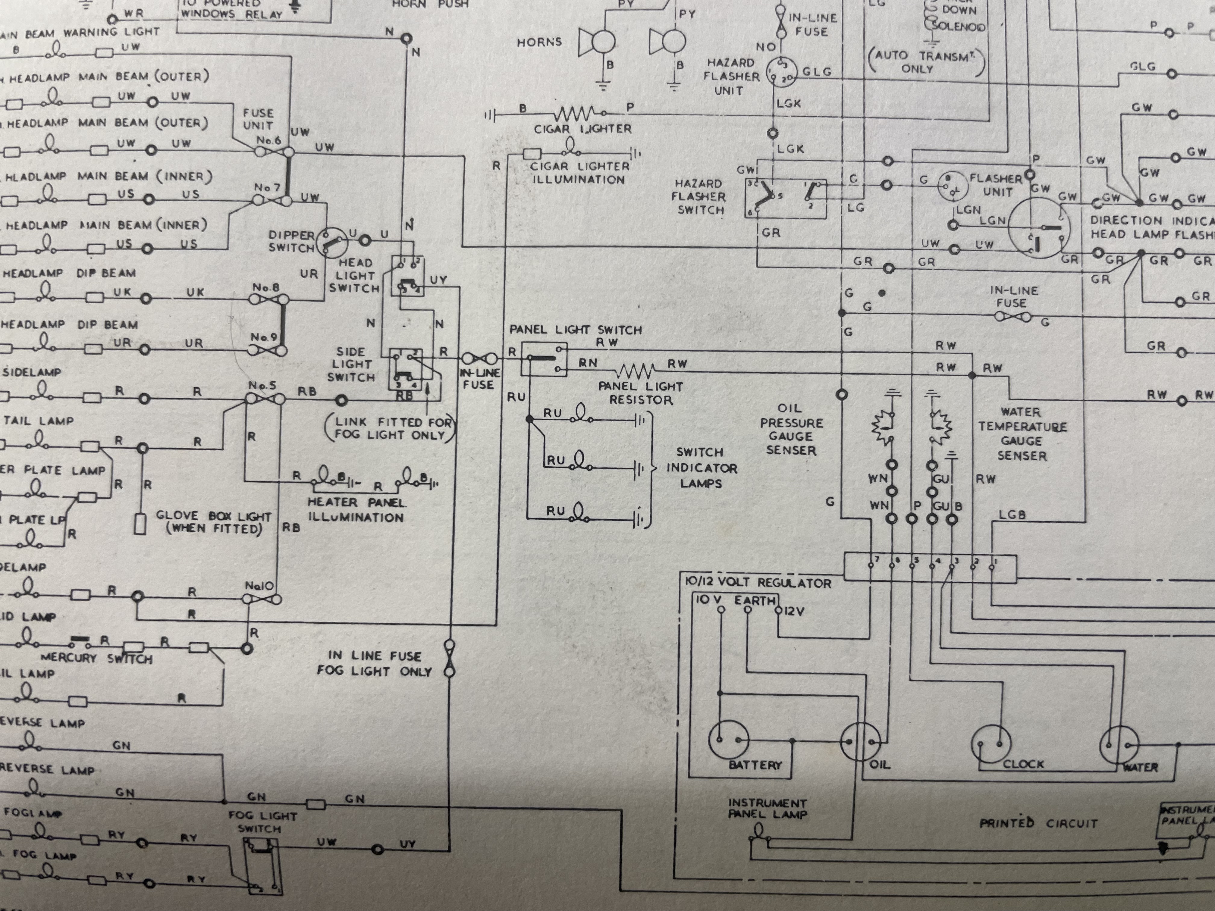
I am a bit mystified by the wiring diagram on the Series One. Fuse 5 does the LH side light/Tail light and num plate light. There is another connection- seen coming from the fuse on the diagram that travels via 211 (heater illumination) and thence onto the next page where it meets a node that supplies the panel lights and feeds back to the panel light switch (13)
This would seem to give two potentially two supplies to these circuits- one via fuse 5 and the other via the panel light switch. In practice, the panel lights work normally with fuse 5 blown/removed, but can anyone else explain the odd diagram?
Russell,
what diagram you using? seems odd so what i have is> fuse 5 & 10 are linked with a R/B wire, fuse 5 out (R) supplies L/h/side & tail lights / glove box & tail lights, fuse 10 (R) out supplies r/h/side & tail, the power supply link (R/B) fuse 10 & 5 supplies side switch (in) & dash light switch (R) out , dash light switch supplies other components.
frank what diagram you have giving those numbers as they aren’t on factory workshop schematics, i reproduce wiring schematics in colour but never used numbers like that, i think russell is not reading it correctly, as i mentioned, fuse 5 has r/b supply in & R out, RB supplies fuse 5 & 10 from the side light switch, which gets it’s power from the headlight switch, from side light switch R out to panel lights, not sure of the confusion there
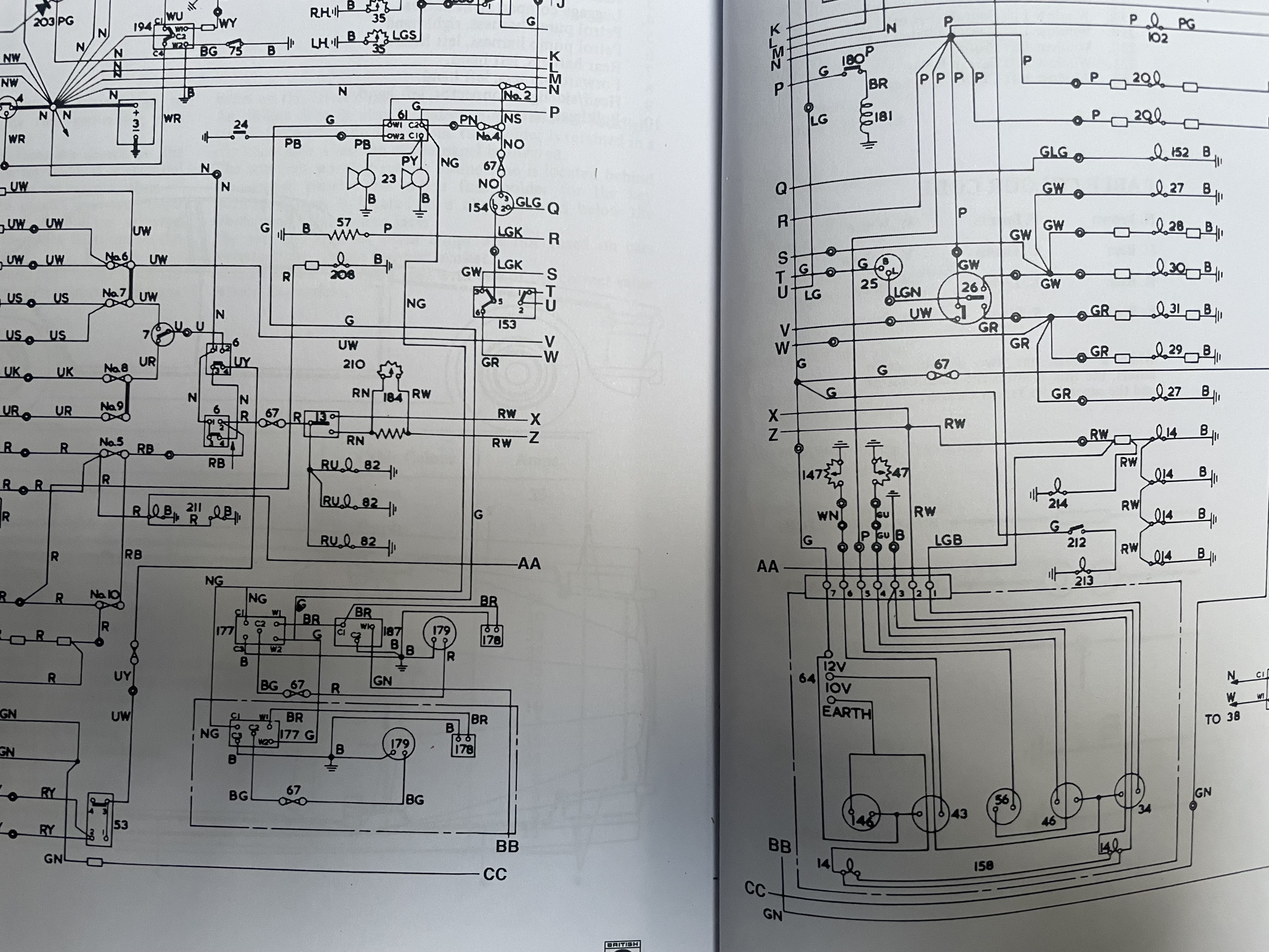
I have the ROM from Jaguar and have included the relevant corner of the diagram, including a marked up version. Also images (showing the same schema) from Haynes
the double connector where the red wire (goes to choke control light) meets the panel lights R/W wire should be a double connector meaning they should be connected to each other only share the same insulator. R/W should be powering the Red to choke light.
I think 212 (green wire supply- fuse 1) is the choke light switch and 213 is the choke light. Annoyingly i don’t have my manual in front of me to confirm.
What is certain is that the choke light works with fuse 5 removed
Russell,
The double A is a reference to follow onto the next page with same double A, if you look down further there’s a double B which then lines up with the double B on the next page even further down is double C…XJ6 S1 had a choke switch no warning light but it could be fitted after same as the glove box light for both models.
Yes, Tom I fully understand why the AA-AA symbols are used. The question is what is that particular connection doing? It seems to connect the tail/side/number plate/ heater panel light across to the other panel lights, No such connection exists- yet appears as a labelled connection on the official schematic