So, my 1971 Series 3 2+2 horns work just fine; however, they’re wired to a push button switch under the dash. I’d like to have the normal steering wheel center horn “button,” or whatever it’s called, operate the horns. It’s nice and “springy.” My question is: exactly where do the two horn relay wires connect to the steering column/wheel? Obviously one wire is a ground, which can go anywhere. The other positive wire needs a steering column/wheel connection, but where?
Hi Ferman,
You need to remove the parcel shelf etc then looking up under the dash you should see a connection to a wiping contact onto the steering shaft by the top column mounting bracket.
Hope this helps
Bob

Hello Ferman,
Only one wire from the Horn Relay is connected to the Steering Column, that being the Ground Wire (Purple and Black); it connects to the contact shown in the circled area of Bob’s picture above. The Push Button when pressed, connects W2 of the Horn Relay to Ground. The active terminal of the Relay (W1) is connected to Fuse #7 via a Green Wire.
Regards,
Bill
Got it and thanks; however, made the connection, but no horn. Upon investigation, I found no electrical connection between the copper piece (circled in red on the photo) on the steering shaft and the pin in the center of the steering wheel horn button, which I believe there should be, right? The springy horn button works OK but doesn’t actually ground the black/purple wire. The flat copper piece (circled in red) rubs on the steering shaft but doesn’t appear to connect with the horn button center shaft. What next? Thaks.
Hi Ferman, check under the horn push button, you should have a brass stud in the center with a spring behind it. If its there, it may be that the top section of the steering column has been taken apart and the brass shaft was not inserted back into its receiving partner lower down the column. This can be hard to do, I struggled to get mine to insert back correctly.
Best of luck
Joe

Hi Ferman, here is a picture of the top of the steering shaft, behind the horn push, this is what it should look like if everything is OK. When its being inserted back into the bottom section, you have to “guide” the bottom by holding the top section, when its being inserted.
Joe.

Hey, Joe, yes, I have that brass stud with the springy top section. And down the column I have the bottom part (rub ring) within the column on which that flat brass clip rubs. It’s just that the two are not connected electrically. I see what you’re saying, that the brass stud needs to be maneuvered to fit into the bottom rub ring. OK, off I go. Thanks.
Hi Ferman, also check that the flat brass clip hasn’t built up “crud” between the clip and the shaft, this would stop the circuit. Disconnect the battery, then get a circuit tester and probe both ends to check if they are connected, (top brass stud to rubbing strip) if there is no connection, it can only be where the shaft is inserted together in the center, it has missed the target while being re-inserted. The reason this inner sliding connection exists, is to allow the steering shaft to be adjusted in length, and still make contact. If you do take it apart, all will become clear. I used a “sacrificial” rubber ring to hold the shaft centered while I inserted it back home. This rubber ring then becomes a permanent resident at the top of the shaft.
Best of luck.
Joe.
Hi, Joe and All. First, yes, I have a good connection between the flat brass “rub ring” and the steering shaft. I checked it with my ohmmeter. Second, I cannot get the brass rod to insert anywhere inside the steering shaft where it makes electrical contact with the “rub ring.” I have also tried using a thin metal rod to poke around, but no electrical connection (by “connection” I mean a circuit as verified by ohmmeter.) My next move is to remove the steering shaft, which I have done before. There is a screwed piece in the shaft, (which, when in place, keeps the steering rod from sliding all the way out but permits it to move in and out a few inches for adjustment). The screw is held in place with a flat brass locking spring; however, I cannot find it again. Do you know where to look?
Hi Ferman, I’m struggling to remember it in detail, but I have an exploded parts page for the steering shaft I could send you if it helps. Are you speaking of the 2 semi circular “collets” that lock the moving part of the shaft to the stationary piece?
I had the same problem of inserting the shaft, and hitting the central target down in the shaft, that’s why I used the rubber ring idea. I found a rubber ring that fits inside the shaft and holds the center contact in the center of the shaft. This then gets pushed up the shaft as the system is mated together. I can send you a drawing of this if it helps.
Let me know if the parts page would be a help.
Best of luck.
Joe.
Hey, Joe, guess you’d better send them both. Thanks.
Ferman
Hi Ferman, here are the disassembly instructions and parts pages for this area. The instructions are not very detailed, but you are way past this point anyway. The parts lists may give you some new information.
The “bottom of shaft” picture gives an idea of what I did to center the shaft while its inserted. I found a rubber ring that is a snug fit between the inside shaft bore and the “electrical contact” piece. This rubber ring then gives support to the “electrical contact” to stay in the center while its being pushed home. Of course the rubber gets pushed up the shaft as its being inserted, and stays there, until the next time the shaft is taken apart.
Best of luck.
Joe.


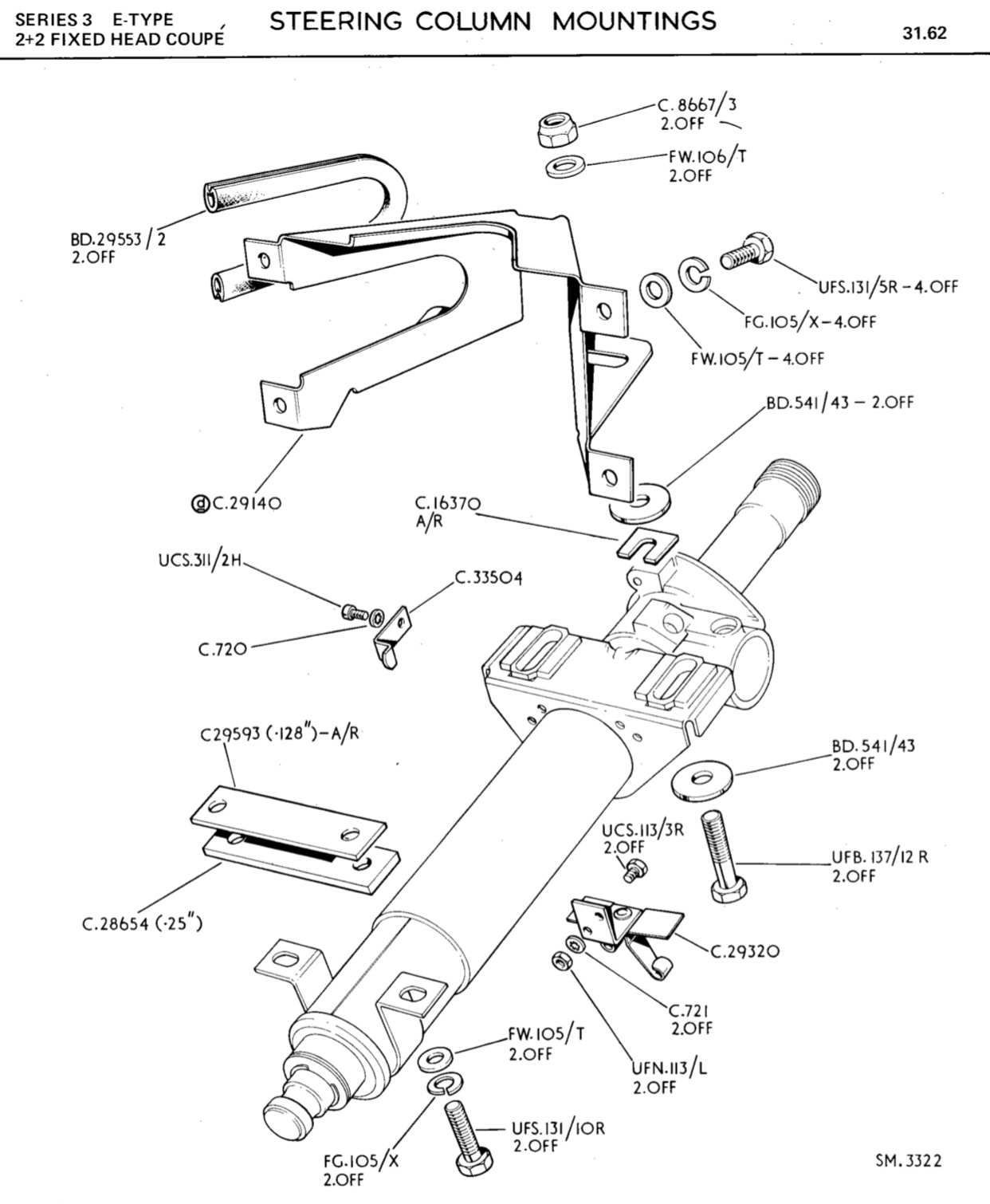

Hey, Joe, the diagrams are very helpful - in particular the second one labeled “Steering Column Mountings.” At the bottom is a small part, C35514, which is the Steering Column Stop Button. That diagram doesn’t actually show where the button goes, but the photo below does. Removing part of the turn signal shrouds reveals the button, which, when unscrewed, permits the entire steering wheel and column to be pulled out. It’s job is to permit the steering wheel to move in and out but not be removed in normal use (Important!). As I’ve done once before, I will remove the wheel and column to see why my horn shaft doesn’t connect with the rub ring. I’ll try your “rubber ring” technique, too.

Hi Ferman, yes, you are correct about that stop button. Remove this and the shaft can be withdrawn fully. I’m sorry, I somehow thought you had gone past this stage already, and had taken the shaft apart. Now it’s starting to make sense. A tip for returning that stop button, make sure when you screw it in, it stops pointing east/west and not north/south. It buts up to that metal ring in the photo, and the ring (when tight) prevents it from un-screwing.
Best of luck.
Joe.
Hey, Joe, well, I’m past that stage now. This morning I removed the stop button and removed the steering wheel along with its attached splined shaft. I discovered the thin metal shaft onto which the larger brass shaft fits; however, checking with my ohmmeter, there is no electrical connection between the thin shaft and the curly brass fitting which rubs on the steering shaft. I didn’t see any way to re-establish the connection, so I buttoned everything back up (yes, including the east-west direction for the stop button.). I believe that is as far as I want to go with this project, unless something new pops up. I appreciate the advice.