Hi Jagies,
I was thinking of a “smart” relay to drive my cooling fans and started designing such to fit in the original Lucas relay housings. The idea was to PWM control the fans and to run them for a while after the engine was shut down. In my prototype design an external (DSB18B20) and internal temperature sensor (NTC) is available and it could also be used to control lights of course. ! Does such device already exist, is anyone of you interested or have you got more ideas ?
Best Regards,
Tom
looks cool tom. please tell us more
Hi Phil,
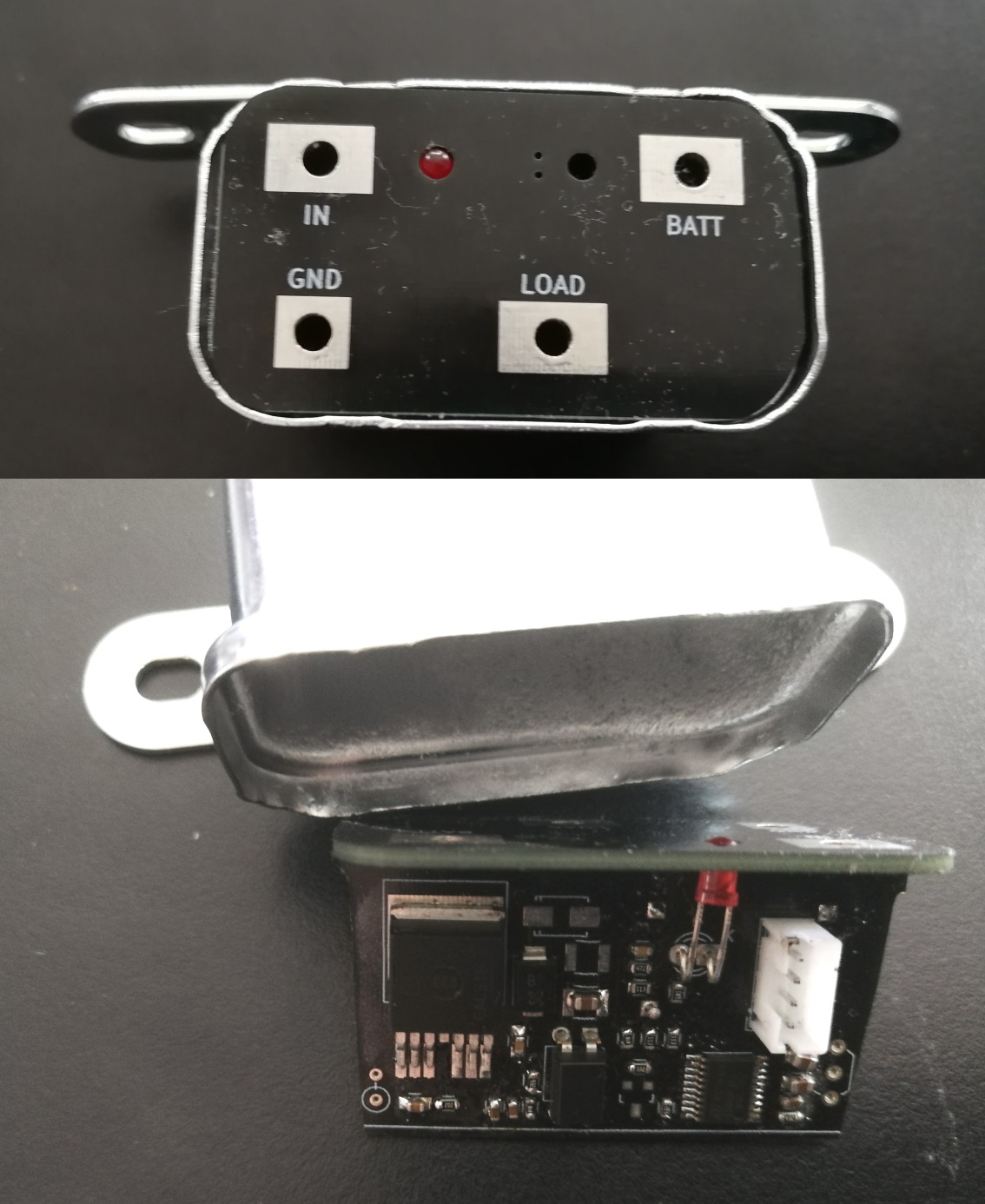
Well the current (prototype) circuit uses a smart highside switch and a small STM8 processor powered by a step down converter. The idle power consumption is 10mA @ 12V and the Infineon highside switch should be able to drive up to 40Amps (ideally). It is the BTS50010 for automotive purposes but the other parts are currently standard parts with non extended operating range. The “IN-Signal” drives an optocoupler and could be driven by the standard relay input (otter switch). I currently use 4 analog channels to measure ambient temperature (inside the relay), the battery voltage, output current (measured by BTS) and an input from a “user-potentiometer” for calibration purposes or similar. There is also a tiny switch for testing or other purposes (setup etc.) and an external DSB18B20 temperature sensor can be attached (maybe instead of the otter switch). The LED is for diagnostic purposes only. As mentioned it was my idea to soft start the fans using PWM and to allow some delayed switch off in certain cases (battery ok, ambient temp high, runtime duration, …). If the power of the BTS50010 is not sufficient I will maybe change to two stronger types paralled.
If one is interested I can provide PCB layout, BOM etc. after I have proceeded a little further and have done some testing before.
Tom. I am not particularly electronic savvy and do not understand what you are trying to accomplish. By smart relay do you mean that you are trying to develop a fan relay that will run for a period of time after engine shut down and is controllably remotely?
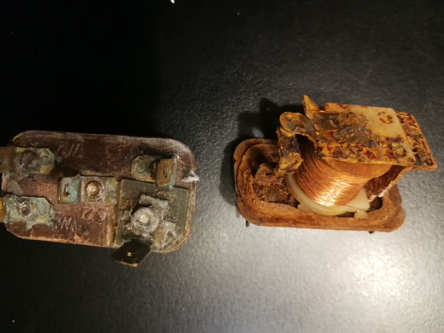
Not remotely but more accurately and maybe switch on/off at a different temperature/state than the otter switch measures. Some say they have their fans always running but I don’t want to do so but don’t want to rely on a piece of bi-metal either. As mentioned this is just a prototype and a replacement for my rotten Lucas relays as well:
And I thought that switching the fan/s on at a lower temperature and with less RPM might be better than running them at full power and then switch them off again totally again without any hysteresis. I have not been driving my Jag for many years now but remember somehow that the fans were quite loud and switched on/off rather often ?! I think switching them on earlier would often prevent from running them at full speed/loudness.
Ok. There is a ready made timed relay that I used for the hisser in a series2 xj6 I was using for a daily driver many years ago. Pretty much any car with a heated rear screen has one. The one I used was from a mid 70’s gm product and it had a relay plus a remote momentary switch to control it. I think later on the 2 units were combined into one. A trip to a pick&pull would probably find you something suitable. In combination with a modern thermal switch to control the fans during driving this would. cover the shutdown period without danger of draining the battery. I do not remember the size of the relay I used but do not think it would fit inside a lucas can. However with the remote momentary switch (think lucas wiper switch) mounted in the dashboard the relay could be hidden anywhere. Would this be of interest for what you want?
No where near as elegant, but I moved the fan relay lead from fuse 6 to fuse 4 which allows the fans to cycle even after the ignition has been switched off.
Yeah, those S2 fans sound like a Cessna 172 on a take-off roll but they usually only cycle twice before shutting down altogether.
I like that this creates some ‘catch-up’ cooling in the radiator when I do brief stops for gas or whatever on long all-day drives.
Have had this in place for years and (knock wood) have not had any issues with the Lucas relay or the otter switch (using a modern Waller [Audi/VW] thermo switch).
1 Like
Use a turbo timer?..
Well it is not about delayed switch off only. The MCU can measure the temperature curve and observe if the fan speed has to be increased / can remain or can be lowered again. Only from a critical temperature on the fan/s would run at full speed and after the drive could maybe run at a lower speed as well. Measuring the battery voltage would tell if the engine is still running or has been switched off already.
I like the Idea , can it be set to shut off if batt voltage falls below a set point for greater than 30 sec , say 12.3 for example. In the case of a weak batt. All in All , Seems this would be a lot better solution than just using a simple adjustable time delay relay. ( upon review of your comments looks like already doing so ? )
Yes there is a “LowBattery-state” and I plan a PID-control monitoring ambient and water-temperature to regulate the speed the fan runs during cruising. PWM control is used in modern cars also to regulate the fan speed but of course they have more information (speed, gear, RPM, temperatures) and can regulate more intelligent of course.
Yes, Nice
I’m Still looking for a decent PWM controller and correct size rotary control for the A/C blower to fit in w existing style knob.
Here’s one that I was intending to buy for a similar application. I think it will accept a generic pot, which can then be adapted to the knob you want.
Things like that are a dime a dozen on EBay. Here is just one of many:
Regards,
Ray L.

Well I did not want to manually remote control the fan by potentiometer but of course this is also a way to go.
ps: If you want to blow reverse
Yes actually just ordered one of those the other day. But I know the Comtrol/pot is tiny. Figured I might just measure it out once i het it and see what the range is i.e. 0-120 ohm. And then find on that will mount nice in the current spot pos w a click on term to signal comp relay.
The car is not on the road yet but a dry test with the fans driven looks fine. I did not yet implement a PID control but have a static table controlling the fan-speed depending on water and ambient temperature. Original fan motors run fine from 20% power upwards and are regulated up to 100% smoothly. Otter or A/C force will override and accelerate to 100% power. I did not yet program an afterrunning cycle yet but that can be done easily.
Boring video of the status quo (and it’s quite late already ) …
Will add more to show reaction to temperature sensor(s). Only showing one fan but two in parallel do not seem to be a problem. 83° of the otter switch may be wrong of course - i did not measure yet.
2 Likes
This is interesting. My LS swapped land rover defender had the same issue and would run hot if I did a couple stops. Never would overheat while on. I looked into this for awhile, but gave up…until now. Perfect idea for my xke restoration…
Hi Steven ! Well I did this while I was waiting for engine parts
I do not yet know which are the correct power settings for different coolant/ambient temperatures (and will maybe implement a self regulating PID controller) but the idea was to run the fans more or less permanently but with reduced power. Another advantage is that it would not cut your fingers when you fiddle around at the fans because it starts slow and painless at about 20% power
The video is very bad but it was LATE already and the water too cold to show the temperature sensor behavior. tbc …