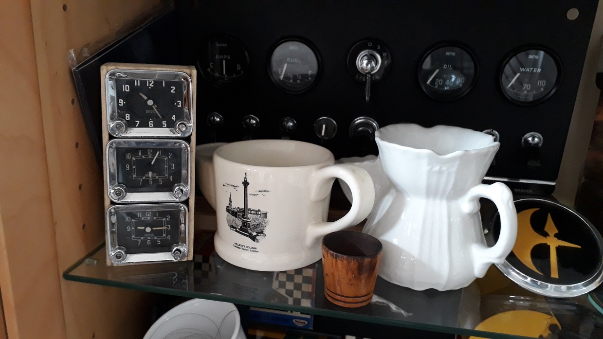
Have a few clocks , are they from the 420?
They are all the same , all but in name , any one now the years ?
What is the best way to test see if they work , don’t think I can connect them to 12v battery can I ?
Have a few clocks , are they from the 420?
They are all the same , all but in name , any one now the years ?
What is the best way to test see if they work , don’t think I can connect them to 12v battery can I ?
They probable need 10v? That’s what the gauges work on IIRC
Smith’s and Yeager had a tie up somewhere along the line.
Early 420 clocks ran off their own independent battery. I’m not sure what voltage this was, so testing one of these with 12 volts might not be a good idea. Later clocks ran off the cars 12v supply. 420s were all negative earth, don’t connect them the wrong way round or that will be the end.
Isn’t there a 10v regulator behind the drop down centre dash on the MK11/S/420 that run the gauges? I can’t find my manual at present so cant check the circuit diagram.
There is a 10V regulator (called the IVR). It supplies the Fuel and Temperature gauges (OP is 12V).
It would make little sense to make a 10VDC clock - to make it work you’d have to have the IVR powered all the time, or an internal battery which would charge at 10V.
The square clocks on the some Jags have a strange battery (Silver Nickel iirc, at 1.35V).
True plus more than that, Andrew. The IVR generates 12V pulses whose time-average is 10V. The clock wants to juice a solenoid when its points close–not wait around for the next pulse. Plus, the exact voltage is of no concern anyway, which is the whole point of an IVR.
Are they by any chance marked on the back with the voltage needed? If not, my go to guy for British car clocks is Mike Eck who sometimes posts here. He has a website you might check out.
Sorry for not chiming in earlier but I am in the process of moving, which will probably take most of a year, and I don’t get to use my computer as often as I would like. Here’s the info on Jaguar clocks:
The earliest clocks were CE type. They were characterized by 4 screws on the back in a rectangular pattern, and they ran on 12V. The earliest ones had a green insulator around the power terminal, and would work with either battery polarity. The later ones had a black insulator and would only work with positive ground, so they usually have “Feed Lead (-)” etched on the back.
The next clocks were CET type. They had one big screw and two little screws on the back and a white power insulator. They used a now unavailable 1.3V mercury cell which was connected with the positive terminal grounded. Since the clock had its own independent power source it didn’t matter whether the car was positive or negative ground.
The next iteration was the CTE type, which looked just like the CET but didn’t have a battery holder on the back. They ran on 12V and by the time they came out I believe all cars were negative ground.
On your rectangular clocks, look for information hidden on the face above the “12” and below the “6”. It would surprise me if any of them worked. Hope this answers your questions.
Thank you all , think I will mount them and place in my display cabinet 
Have them all set to different times, with the names of different cities under them…