Thanks a lot, Frank!
I’ll try to translate this to the electrician/fitter.
Hi Jochen,
I am temporarily back on Jag-Lovers after 10 years. I was a serious contributor to Jag-Lovers Forum when I owned both a 84 XJ6 III and a 92 XJS convertible which were used as daily drivers, but remember you either love them or hate them and I got to the latter after constant electrical issues. Have been driving a 2004 M-B S500 ever since, and BTW if you want to see a how to setup an easy to use knowledge base have a look at w220.ee, but I digress.
I am helping a friend who is restoring a late 78/79 XJ6 4.2L. It hasn’t been run for 15 years and is in super original condition.
However when the ignition key is turned to #3 (IGN) the starter motor operates. We have spent two extremely full days reverse engineering the car and found it matches closely the wiring diagram which was gratefully posted above.
As I understand it the 295 PUMP RELAY activates via a W (white) wire with 12V power from No. 4 fuse but only when the 42 OIL PRESSURE SWITCH closes once the engine is running and has built up oil pressure. That all makes sense. The 12V power doesn’t actually go through the No. 4 fuse but originates from the ignition switch when it is turned to # 3, (IGN).
We have discovered that if the small WR (white red) wire from the 194 START RELAY which goes to the 295 PUMP RELAY is removed it seems to fix the ignition start issue. The car will not start though as I suspect the 183 AMP on the 40 DIST is blown but that is a separate issue.
Referring to the diagram the common terminal on the 295 PUMP RELAY, designated 30 on our physical relay and as C2 on the diagram, has a W (white) wire going to the 250 FUEL CUT OFF RELAY and to the 294 FUEL CUT OFF VALVE, but, and this is the issue, it also goes to the 38 IGNITION SWITCH #3 (IGN). The diagram shows this and the car tests this way. If it is meant to be like that why didn’t they just connect the W wire to the coil and fuse No. 4 as above?
What it means though is once the ignition switch is turned to # 3, (IGN), 12V from the common terminal feeds through the normally closed contact via the WR (white red) wire to the 194 STARTER RELAY and then directly to the starter solenoid hence cranking the motor. Obviously something is wrong but I cannot figure out what. The diagram just doesn’t make sense.
Any help much appreciated.
Regards,
Brian from Down Under
Sorry I haven’t posted for so long I have forgotten the tricks, and besides I am now quite old.
Should have included a link to w220.ee as per W220 Knowledge Document
Also a diagram may help identify my concern re the published Wiring Diagram.

And I also wanted to share with you my Wiring Diagram Components Designation document. This has all the components listed on the original 78/79 XJ6 wiring diagram but in both alphabetical and numerical order.
Late 78 79 Jaguar XJ6 Component Designations 20190324.pdf (113.8 KB)
Welcome back, Brian,
no need to apologize and thank you for the efforts as regards the list of components - indeed, it has taken me minutes sometimes to find the number and location of say, the power windows thermal breakers.
From what you’re writing I understand you did your homework:-) and found that the car and its ignition are unmolested. That makes a good starting point. I’m not understanding your problem fully, I’m afraid:
You’re writing the starter motor operates - which is good. Obviously, though, the engine won’t start. But then you write that if you remove the white wire from the starter relay to the pump relay it fixes the ignition start issue. What does this mean - in particular as you continue to state that the car won’t start?
Maybe you give us - Frank and many others know a lot more! - some concrete information of how the car reacts on the turn of the key. If the starter operates, but the car won’t start after 15 years of sitting, I’d be more concerned about the fuel side. Did you check quality of the fuel, protect the pumps against rust from the tanks by adding filters, fuel at the carbs? Are the carbs free (sometimes they really gum up)? How about ignition? Do you have spark at the plugs, power at the coil etc.?
Good luck and keep us posted
Jochen
INAKI, IMHO,
Its very simple if you want to keep a JAGUAR dizzy .
Use a complete series 3 , it has the amplifier box and matching coil
All your doing is the hot key wire and the red wire fron the amplifier to the positive and the black to the negative.
They are now upgraded with GM/DELCO diodes for much greater reliability.
Now a days there are MUCH better options, 123 dizzy or petronix.
They all just bolt in and your done.
I had a series 3in my 70 etype for 30 years before I went to something more modern,
Good luck any help just pm me…….
gtjoey1314
they are keyed so you cant screw up the position…
I like the idea of converting to a Series 3 distributor with ECM but it is not my car. Before we explore that path I want to better understand the wiring diagram for what we have got now
I know that it is quite complicated and not helped by the fact that the circuit diagram is not very clear in places and I also believe has a couple of mistakes, but I will post about that later.
The wiring diagram does not show which contacts on the 295 FUEL CUT OFF RELAY are N.O. (normally open) and which are N.C. (normally closed). Our inspection of the actual relay (a red relay) indicates that C2 is the common (designated 30 on the actual relay) and C3 is the N.C terminal (designated 87A on the actual relay).
The 295 FUEL CUT OFF RELAY terminal C2 (30) is connected to the 294 FUEL CUTOFF VALVE. These names imply that when 294 is energised it will cut off the fuel. But from a safety point of view it would make more sense to have the fuel cut off when there is no power ie when the 294 valve is unenergised or in its normal state. If this were the case it should be called a fuel turn-on valve.
Qu. 1: Does the 294 FUEL CUTOFF VALVE have to be energised to turn the fuel on?
The 295 FUEL CUT OFF RELAY will only energise when the 42 OIL PRESSURE SWITCH is closed. The wiring diagram is not clear about this point.
Qu. 2: Is 42 normally closed and goes open when there is oil pressure or vice versa?
I will come back with my other issues when we get past this point.
TIA
Brian
**
Questions arising, Brian: What happens when you turn the ign key to #4…?
The simplest explanation is that the ign key shorts electrically inside between ‘run’ and ‘crank’ - or the white/ yellow is connected to #3 position instead of #4. (In the latter case; there will be no crank in #4). Either fault will power the white/yellow in #3, activating the starter solenoid relay…
The starter relay activates the starter solenoid - which basically powers up white/red wires. The relay will activate whenever white/yellow is powered…
In carbed versions a fuel safety relay is included - to prevent fuel pump(s) running unless the engine is turning, or with ign key to ‘crank’. The oil pressure switch grounds the relay when oil pressure is present. The relay is powered by white, which is powered with ign key is to ‘run’ (#3). With oil pressure present the relay activates the fuel pump(s) in ‘run’.
In ‘crank’; the fuel pumps are run directly by the white/red from the starter solenoid relay.
In short; the cranking circuit involves the ign key, starter relay and starter solenoid. The fuel pump circuit is a separate function, but uses the starter relay as a power source in ‘crank’ - and the fuel relay as a power source in ‘run’…
Depending on where the white/red is disconnected it may cut power between the starter relay and the starter solenoid…
Mind you; exotic faults may be conjured up - but the gist is that cranking can only occur if the starter solenoid is powered. Which generally involves the starter relay…
Frank
xj6 85 Sov Europe (UK/NZ)
**
Thanks Frank,
I understand everything you say.
Re your question. We didn’t try turning the key to #4 as we got such a shock when the starter operates in #3.
Re your statement quote The oil pressure switch grounds the relay when oil pressure is present. Unquote. So that means the 42 OIL PRESSURE switch is N.O. and only closes when there is oil pressure. That sounds reasonable.
Re your statement quote With oil pressure present the relay activates the fuel pump(s) in ‘run’ Unquote. According to the wiring diagram, the 295 FUEL RELAY directly powers the 294 FUEL CUT OFF VALVE So I think to answer my own question posted above, the 294 FUEL CUT OFF VALVE is actually a fuel TURN ON valve where the valve opens when it is energised and allows fuel to flow to the carbies. That makes sense from a safety point of view. No power - no fuel!
My big issue with our car and the wiring diagram is that it seems as though the 294 FUEL CUT OFF VALVE is also connected via a W (white) wire to the 250 INERTIA SWITCH as per the diagram. However the wiring diagram also shows the 250 INERTIA SWITCH connected to the 38 IGNITION SWITCH #3. This doesn’t make sense and will cause the starter solenoid and starter motor to operate with ignition switch in #3 which is what we find in the actual car. Cannot explain how it comes to be that way other than something has failed. But so far the car matches the wiring diagram even though I think the diagram is wrong.
I plan to do more tests on the car when I can next get access to it.
I have spent all day analysing the wiring diagram and it seems to make more sense if there is no W link 250 to 294 .
The first figure shows the main parts of the wiring diagram and this agrees with what we have tested so far in the car. The red lines are the links indicated in the diagram.
Later note: Diagram removed. See note below.
The second figure shows the W link 250 to 294 (X - - - X) NOT connected, and Ignition OFF ie no oil pressure and 294 FUEL CUT OFF VALVE NOT energised thus no fuel flow. The 295 FUEL RELAY is NOT energised.
Later note: Diagram removed. See note below.
The third figure shows the situation when CRANKING with the W link 250 to 294 (X - - - X) not connected, and Ignition ON (BLUE dots) and Engine Starting (PINK dots) but no oil pressure yet and 294 FUEL CUT OFF VALVE energised to turn fuel ON. The 295 FUEL RELAY is still NOT energised until there is oil pressure.
Later note: Diagram removed. See note below.
The last figure shows the W link 250 to 294 (X - - - X) not connected, and Ignition ON (BLUE dots) and Engine Running with oil pressure (42) and 294 FUEL CUT OFF VALVE energised to turn fuel ON. The 295 FUEL RELAY is now energised.
Later note: Diagram removed. See note below.
Any feedback much appreciated.
Brian
Later Note: Now that we have fixed our issue with the 1978 Jaguar XJ6 Series II 4.2L I have removed my previous uploaded diagrams as they were full of errors and misassumptions. I will post a complete summary of how the Fuel and Start Electrics works. Brian
Brian, The locking column of a series 2 is like a series 2 etype.
Its junk.
The switch is a cheap piece of plastic with a copper wire running through it that is running ALL the voltage through it.
They crap out very very easy and even melt.
Can you ISOLATE THE SWITCH with a STANDARD key switch.
I think your problem will be solved.
Theres a starter relay switch as well on your series 2 but…unless the GROUND on the relay is broken.
Go back to the switch.
GOOD LUCK.
GTJOEY1314
P.S. The schematic is correct, the voltage I told you about goes through the switch along with the fuel pump…
Why, because they believe in a HOME RUN for the fuel non fused so the pump wouldn’t cut out.
Many of us ran a fuse in line at 30 amp for back up as the key unit would MELT.
GO BACK TO THE KEY SWITCH.
Ahh … now it makes sense - sorry, I overread you wrote that the starter operates on ignition already!
Then it’s perfectly clear - after 15 years this engine urgently wants to run;-)
No, I’d also put my money on the ignition key switch. It’s maybe not as bad as described, but after 40 years and maybe some serious forms of keyring abuse they go bad. So far I’ve only encountered the no-go failure mode, but Ignition and Start might just have shorted as well. What happens, if you bypass the key switch?
Best
Jochen
75 XJ6L 4.2 auto (UK spec)
Any auto parts store has a STANDARD key switch with a key………
It will have the same leads ,try it , it will be your answer……
**
Bear in mind that the oil pressure switch relates to the fuel relay and fuel pump/feed action, Brian - it has no bearing on the cranking in #3 key position. Have you actually physically found the fuel cut-off valve - I’m not sure you have one. Jaguar didn’t faithfully update the wiring diagrams as things physically changed…
However; If the engine still cranks in #3 key position, this must first be rectified - this malfunction may have bearing on other electrical problems. I fully support Jochen and Limongelly - the focus should be the interaction between the starter relay and the ignition key. Working in other areas with dis- and crossconections is doomed to frustration if the fault is in the key…
Cranking occurs when white/yellow on the starter relay is powered - which should only occur with the key to ‘crank’ position. If that wire is powered in #3 position; it is simply wrong - and the cause must be identified and remedied. The fault may be in the ign key as said, but the anomalous cranking must focus on the starter solenoid…
Generally about the ign key; it has main power, brown, in - and key directs this power internally into various circuits depending on key position. In ‘run’; white circuits are powered - basically powering all engine management systems, like ignition and fuel pumps.
As a safety feature, the white circuit goes from the ign key through the inertia switch. If the inertia switch is tripped; all white wires are left unpowered - and the engine can’t run.
In ‘crank’ the white/yellow circuit is powered, operating the starter relay and overrides some safety features, like the fuel safety relay. But the white circuit is also powered in ‘crank’ - ensuring that ignition functions, and ensures a smooth transition when the key is returned to ‘run’ as the engine starts
Frank
xj6 85 Sov Europe (UK/NZ)
**
I can only add a bit from my recent electrical travails. Although my car is no longer powered by the DOHC, much of the Jaguar electrics remain.
-
Starter would crank in run at times!!! Did in more than a dew starters!!!
-
A revised crank circuit was the cause. Back feed!!!
-
Back to a semi original. Diodes on the starter relay. Two, I don’t recall on which pins???
-
That fixed that issue!!!
-
Missing volts at the driver side fuse box. No brake lights, etc…
-
Internitrtant engine drop out, radio drop out…
6 NOS ignition switch via David Boger. Fiddly to install, but I got it!!
WOW!!! switch much tighter. Issues vanished.
Old switch a victim of years and too ,many keys on the ring, I guiilty!!! Reduced it. Better, but not optimum…
So, now so long as the battery is up, it cranks and fires immediately…
Carl
Thanks for all the replies.
The Ignition switch seems to work perfectly and after isolating the starter circuit we have tested the wires coming from it. All seems perfect.
What I was trying to determine with my coloured wiring diagrams above was to understand exactly how the system works. Not easy given that the schematics seem to refer to several XJ6 versions, but the detail printed on the back helps for a late XJ6 Series 2 with carbies.
The car in question seems to match the above published wiring diagram. However just going by the way the components are drawn there is a fundamental problem. The link X-X shown in red will cause a feedback path and the starter motor will energise with ignition switch at position #3 (IGN ON). If you analyse the circuit with the X-X link removed as per my coloured diagrams there is no feed back path. Carl has given me the clue to what may have failed. A BLOWN diode in the 295 FUEL CUT OFF RELAY would cause the problem. The wiring diagram does not show any diodes but we will open it up and investigate if it indeed has diodes and their current state.
Re Frank’s comment
We haven’t actually looked yet, so that is another job to do. However based on the published wiring diagram with the X-X link connected and with the car running with oil pressure, the fuel relay will provide power to the 250 INERTIA SWITCH and then the 140 FUEL TANK CHANGE-OVER SWITCH, which makes sense as long as there is no feedback path to cause the starter to operate. I will attempt to demonstrate the feedback path.
Later note: Diagram removed. See note below.
Note these conditions in this diagram;
- 38 IGNITION SWITCH #3 (ON),
- 42 OIL PRESS (N.O. no oil pressure),
- 295 FUEL RELAY (not energised),
- 194 START RELAY (not energised),
And critically;
- 4 STARTER SOLENOID (energised when it shouldn’t be!),
- 5 STARTER MOTOR (cranking when it shouldn’t be!)
In words; with the ignition switch turned to position #3 (ON), current can flow from the battery through the 38 IGNITION SWITCH terminals 2 and 3 to the 295 FUEL CUT OFF RELAY terminal C2, in the process powering the 294 FUEL CUT OFF VALVE if fitted.
295 FUEL CUT OFF RELAY terminal C2 is the COMMON terminal and when not energised the current will flow out of the 295 FUEL CUT OFF RELAY terminal C3 (N.C.) and make its way via the small WR (white red) wire to the terminal C1 on the 194 START RELAY which at this moment is NOT energised.
The current also makes it way via the large WR (white red) wire attached to terminal C1 on the 194 START RELAY to the 4 STARTER SOLENOID which gets energised and the 5 STARTER MOTOR begins CRANKING the engine. (Note the 194 START RELAY is still NOT energised.)
This is the essence of the problem as the starter motor operates when the ignition switch is in position #3 (ON) (as distinct from #4 (START)).
From my electrical engineering experience a blocking diode fitted at the 295 FUEL CUT OFF RELAY terminal C2 would solve the problem. There may be other solutions of course.
Later note: Diagram removed. See note below.
MY CONCLUSIONS
The wiring diagram is not complete in that it doesn’t show a blocking diode to stop the feedback path and the car in question has a failed blocking diode. The next job is to see if we can find it.
Regards,
Brian
Later Note: Now that we have fixed our issue with the 1978 Jaguar XJ6 Series II 4.2L I have removed my previous uploaded diagrams as they were full of errors and misassumptions. I will post a complete summary of how the Fuel and Start Electrics works. Brian
**
The inertia switch is always(!) powered (has 12V) by the white wire from the ign key in ‘run’ or ‘crank’, Brian - it does not(!) receive power from anywhere else; it delivers power. All engine management systems are powered via the inertia switch - which, when tripped, will cut ignition and fuel pumps…
The inertia switch has no relation to cranking in this version - cranking will be possible even if the inertias switch is tripped. (This was introduced on V12s later…)
**
The 'C’s on the starter relay are not(!) connected together until the relay is energised. Cs has fat brown (main power in), fat white/red (to the starter solenoid). The relay simply connects these together as its prime function - to power the starter solenoid, which connects the starter to the battery.
A thin white/red on a ‘C’ may be used to override the fuel safety relay (or whatever) in ‘crank’. And maybe some wire on another C used to ‘do something’ during cranking. With carbs and electronic ignition; a white/blue to a ballast resistor - related to ignition…
Crucially; the Cs are separate(!) until relay energises - otherwise no crossfeed. If the relay fails ‘on’ - the engine will crank continuously until battery is exhausted or disconnected…
I suggest you disconnect the white/red solenoid connection from the starter relay. Using a test lamp you can verify power at various points with ign key in various positions. Particularly white/yellow at the starter relay - which should be unpowered in ‘run’ and powered only in ‘crank’.
With this resolved, the test lamp can be used to locate other electric faults - if the engine refuses to start/run…
But first; disconnect any jumps - and reconnect all connections to initial state. You are at present simply working the diagrams in the ‘wrong’ direction - assuming a feedback causing unwanted cranking. Which is not the case from the areas you mention…![]()
Frank
xj6 85 Sov Europe (UK/NZ)
**
Ah another good clue because I am certain when we tested the actual relay it behaved as a normal change over relay (C1 was N.O., C2 was the common and C3 was N.C.) and I complained about the stupid representation on the wiring diagram. It certainly wasn’t obvious by looking at the diagram how it is supposed to work.
If as you say Frank, it has two N.O. contacts (C1 and C3) which connect to the common (C2) when energised, it would give the same result as having a blocking diode on C2, and no feedback. We will retest the relay asap.
BTW we can stop the feedback by disconnecting the small WR (white red) wire.
We haven’t introduced any jumps. The car is wired as we found it and matches the wiring diagram. The links I showed in red on my diagrams are meant to be there according to the wiring diagram.
Regards, Brian
**
The crucial point is to stop the engine from cranking in ‘run’, Brian - does that stop with the small white/red disconnected from the starter relay…?
Which would be odd as it should be unpowered unless the relay is activated. If somehow powered in ‘run’ it will feed the solenoid through the co-connection with the fat white/red.
With the small white/red; disconnected; try cranking. If normal (the engine may not start); it implies that ‘somewhere’ the small white/red is wrongly connected at a component; likely to a white wire - or a short ‘somewhere’.
Bear in mind that the pumps should not run in ign ‘run’ position - the fuel relay is not active without oil pressure switch ground. The intent of the thin white/red is likely to power the pumps in ‘crank’ only - there should be no power on it unless the starter relay is activated…
Is there a white/blue on the starter relay? Have you found the fuel cut-off valve - and with what wire colours?
Frank
xj6 85 Sov Europe (UK/NZ)
**
Hi Frank,
Sorry, I am getting old and a bit forgetful so when I said [quote=“ricebubbles1, post:37, topic:367622”]
because I am certain when we tested the actual relay it behaved as a normal change over relay (C1 was N.O., C2 was the common and C3 was N.C.) [/quote] I was correct but I was referring to the 295 FUEL CUT OFF RELAY ( the red one). The actual physical relay has the designations painted on the end. BTW the ‘C’ and ‘W’ designations are Jaguar inventions. The more normal convention is to use numbers such as 30 for the Common ie the changeover wiper in a relay. 87A is the designation used for the normally closed (N.C.) contact when the relay is unenergised, etc.
I am 100% sure that the next diagram displays the relay designations and how they operate correctly as I have actually tested them. The OEM wiring diagram is poor in this regard especially for the 295 relay.
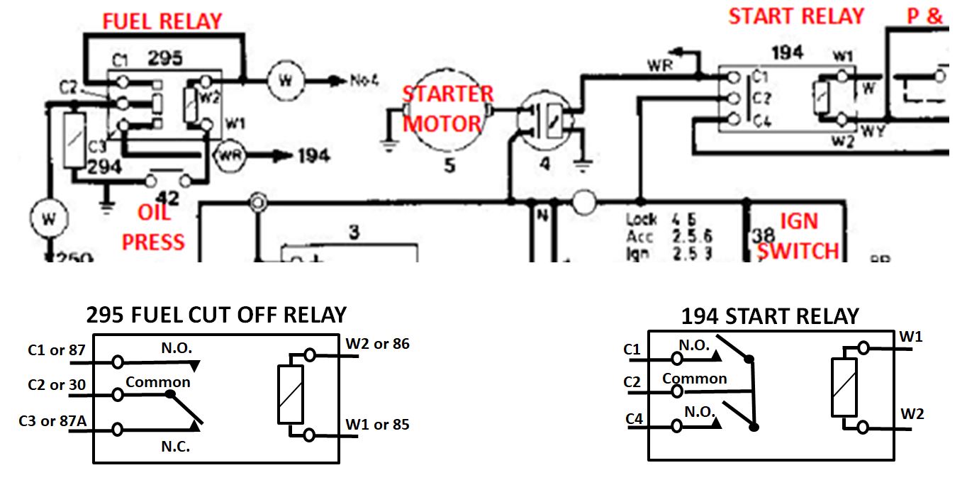
The 295 relay is referred to as a single pole double throw (SPDT) relay. The 194 relay is a double pole single throw (DPST) relay.
Re your “The crucial point is to stop the engine from cranking in ‘run’”. Absolutely and yes, removing the small WR (white red) wire stops the engine cranking in run (ie Ignition switch position #3 IGN ON).
Re your “Which would be odd as it should be unpowered unless the relay is activated. If somehow powered in ‘run’ it will feed the solenoid through the co-connection with the fat white/red .”. That is not quite correct. If you check the above relay designations diagram, the 295 relay still has a connection from C2 (30) to C3 (87A) when not energised. The N.C. connection. The 295 relay doesn’t have to be powered to feed voltage back through the small WR wire to the 4 STARTER SOLENOID.
This is the feedback issue I have been referring to all along. Note the starter motor is cranking with BOTH relays unpowered… Only the 4 STARTER SOLENOID is energised due to the feedback of 12V via the small WR wire.
So the bottom line now is that my previous conclusions haven’t changed from Post 34.
MY CONCLUSIONS
The wiring diagram is not complete in that it doesn’t show a blocking diode to stop the feedback path and the car in question has a failed blocking diode. The next job is to see if we can find it.
I have yet to visit my friend (remember it is not my car) to check for a diode.
Regards,
Brian
**
That depends on where the small white/red is connected to the starter relay, Brian. What are the colours on your starter relay Cs - and for that matter on your fuel and fuel cut-off relay. My diagrams simply differs from the ones you show. And it does not help that the connection to the fuel pumps, traditionally white/green is not shown. Which is odd for fuel related relays…![]()
We agree that there should be no cranking in ‘run’ - and that the fuel relays are not meant to activate the starter solenoid…right…?
As a diode is not shown (on small white/red?) I doubt if you find one. And putting in a diode where none should be is unlikely to be the correct solution…?
Frank
xj6 85 Sov Europe (UK/NZ)
**