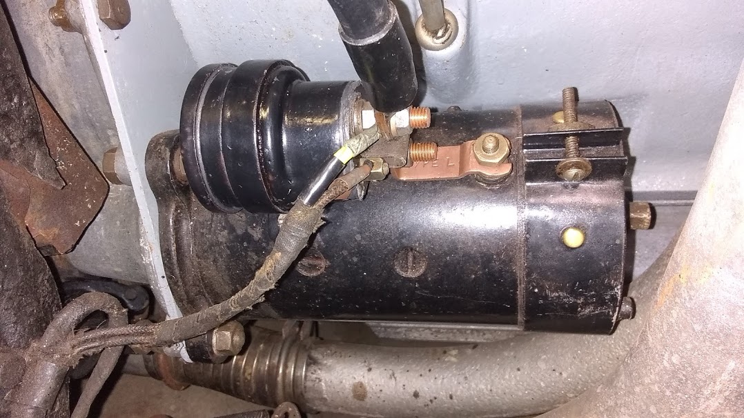
Well, my solenoid on the '38 SS has given up the ghost.
The Lucas part number on it is 760039 with a date 3 48 and a model ST800 and 12V.
I found it in the 1939 Lucas catalogue.
This model has curved feet to sit on the starter, where ST810 or 760080 listed in the Mark IV SPC is identical but has flat feet.
I’m wondering if anybody has taken one of these apart, and repaired it?
There is a solder joint on the bottom, apparently a ground for the coil.
After removing the solder, it looks to me like the rear cap can be taken off. There is a tiny copper nail head in the middle of the cap. I don’t see anything else holding it on, so what could there be? Glue or epoxy?
No, it was all assembled from the other end with the large cap off. But when the nuts are removed the copper studs wiggle a little bit, so I suppose they have a head on the other end which fits into a recess in the Bakelite.
I don’t know , but it sounds like it may be a copper rivet ,
Place it in a vice , so bottom part is lose , and tap the copper part with a centre punch !
If that don’t work drill it out !
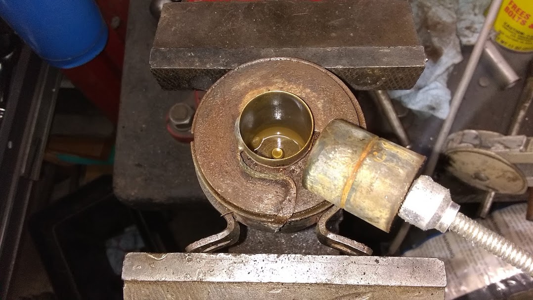
Well, I got it apart. I heated up the top cap a bit with a propane torch, then with a screwdriver, popped it off. It was just held on by annular deformation, sort of like a soda pop bottle cap. Turned out the copper rivet was not important, just holds a spring finger tab, no need to remove it.
Next is a steel plate, which was tight in the housing, so I tapped lightly on the copper studs until it came out. That was tricky because you are working against spring force.
There is an insulating cup and a couple of insulating washers in there so you have to be careful not to wreck them.
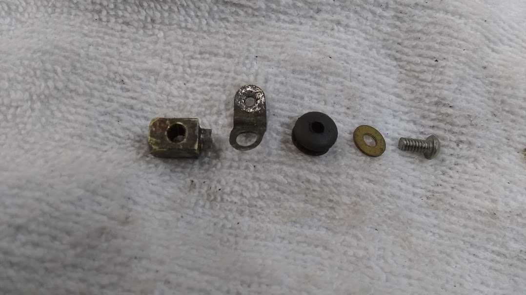
Here are the offending parts. The copper ring is insulated from the center shaft. The center shaft and copper ring are pushed down by the steel slug when the coil is energized, and the ring makes contact with the two copper studs.
Every time you run the starter there is a spark across these terminals which makes a little dirty spot. Eventually you have no more clean spots and no current will pass to the starter motor.
It looks like I can clean these up and reassemble the thing. The trick will be to ensure that nothing touches ground that shouldn’t. The insulation around the little side terminal is a bit damaged so I may have to come up with something better there.
A good step-by-step run down on dismantling these solenoids, Rob, thanks. It looks like yours was originally a zinc coated steel body. You could consider that while it is apart you could buff out blemishes and get the two body parts re-plated in grey zinc, and it would look like new.
My solenoid let me down in busy traffic one day and was very intermittent in operation. Like you did, I found the end cap can be removed after de-soldering the blob. I removed it cold by gentle taps on a flat edged drift as the interference fit is minimal. I thought this solder was just for locking the two parts together. However, I found it was to solder the braided earth strap to the body, and that was where I found the fault. The end of the copper braided tab is squeezed between the cap flange and body in assembly, and should project a bit past the cap flange when assembled. The two body pieces and the braid are then soldered together with one small blob. The fault in mine was that the braid was not exposed enough and did not get included in the solder, so it relied solely on a dry metal-to-metal contact.
It would be a help if we could find out what the resistance should be for the coil so that this can be checked to see if there is any internal fault.
Thanks Peter. So my propane torch was not necessary except to desolder the ground wire.
I too noticed that plating on the body but didn’t know if I should mention it, don’t know if a plated '48 solenoid would be right on a '38 car.
I get zero Ohms on the coil wire, which just tells me it is one continuous wire as I expected, and it is soldered to the internal brass sleeve where the steel slug slides. That part was working before, it just wasn’t passing current to the starter. The wire looks like it is coated (i.e. normal motor wire) and may have some insulating wrap between layers. It has an insulating sleeve where it passes up to where it is soldered to the small side terminal.
Raining here today and I always do my sandblasting outside so no sandblasting the steel parts until tomorrow.
I expect that they should be black, and replacement units after production were plated, a process that seemed to be becoming standard from about the early '50s. The ones on my '47 and '48 cars were black but in my spares, I had both, but only one was plated. I think early ones were date stamped but I can’t recall specifically whether it appeared to be a traditional Lucas stamping or just some numerals at the end of the stock number string that coincided with a typical year. Zero Ohms - can’t get better than that. There is also a paper insulating separator between the outer terminals and which frets over time. I was lucky in that my father was an electronics whiz-kid and when I cleaned out his workshop I retrieved the remnants of insulating cards to make various insulating separators. Without this, it is easy to short across the terminals when wielding a tool.
The stub remaining was solid, not drilled. I decided a screw through the bottom would work. Dug out my set of tiny taps left to me by my wife’s grandfather, a gunsmith doughboy in WW1.
Decided to paint it inside and out for rust prevention.
Reassembling, found my #4-40 UNC x 1/4" long screw was too short, used another 3/8" long. The head has to be covered with RTV silicone so the copper ring doesn’t contact it.
Contact ring with springs and steel backing disc installed.
Coil wrapped with new electrical tape and installed.
Little wire fed up through the little holes and soldered to the tab.