still have yet to remove the fuel filler neck, got distracted with a garage upgrade. Christmas in July, if you will.
4 ton split ac. 2-24k heads. should hlep with the az summers a tad…


1 Like
and moved on to some rust repair. cut this out and replaced it with a piece i cut out of the series 3. it was not an easy weld. either was spitting back at me or burning through the 46yr old metal.
why do people repair rust with mesh screen and then attempt to cover it up, poorly?
will be replacing the fuel tank cover with the S3 piece as well due to rust.

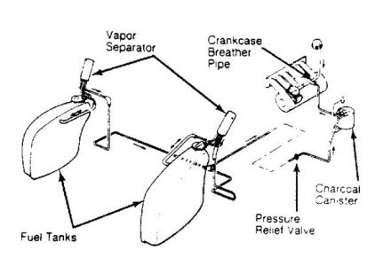
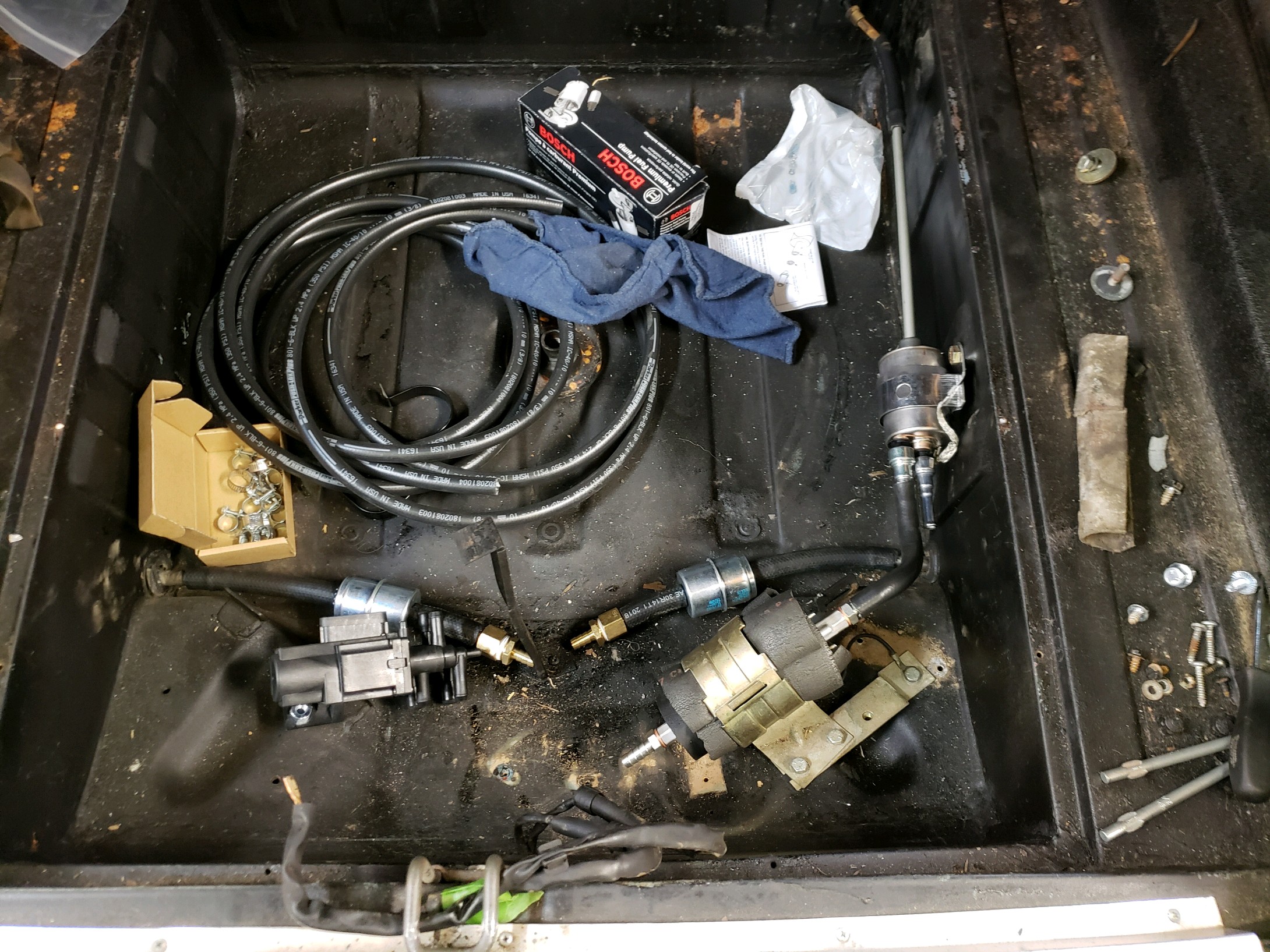
seems i am having a hard time wrapping my head around what i need to do to upgrade to fuel injection. thought i needed the S3 tanks for fuel returns. that does not appear to be the case, unless my S3 is not in factory configuration. i am now on the school of thought that i do not have to swap tanks and here’s why. If you look at the filter pic below, it should be apparent. This is how my S3 is. 2 lines from either tank to switching valve to pump to brass 3 port fitting with an inlet for pump, inlet for return and outlet to front of car. the unused fuel does not get returned to the tanks. there are extra tank fittings on the S3 near the top that are not present on the S1. these are for vapor separators. if i swap everything i need to swap charcoal canister, vapor separators, and pressure relief as well, no?
or keep the S1 tanks and not worry about that mess as the S1 tanks are vented, whereas the S3 are non-vented here in the states.
Where would the vapor cans in the pic be hidden? i’d like to run new rubber lines to them if i swap them. does the S1 have vapor cans hidden somewhere as well? where does the small rubber line go that is on the front of the filler neck?
is my thinking flawed? i know i was originally way overthinking this, but it suddenly seems much more simple if i just keep the S1 tanks and feed the return back in like stock. don’t recall where i read/heard i needed the S3 tanks for the return lines. there aren’t any.
open to suggestions and corrections on my thinking, thx!

I am a bit confused.
You have three fuel lines to deal with if going to the SIII EFI plumbing.
- Fuel pup to engine injectors and PSI regulator.
- Regulator to tank return plumbing
- Closed tank vent. Vents to engine via the charcoal cannister.
The diagram depicted is the latter.
I hope you are not considering uysing it as a return and ditching the vent for an old tech vent to atmosphere.
Carl
I have added a photo showing the use of the GM regulator and pump - plus the use of the Pollak 6 port
return valve… this gets rid of all the Jag tank switching stuff. I have used this on two Lumps and it works perfectly.
Using the GM stuff that is cheap and readily available is the way to go… courtesy of Andrew at Jag Specialties!

One goes in, one goes to the filter, one goes to the canister: this is the combined check-and air separator valve. The return line starts at the pressure regulator, goes to the LH side around the engine, and runs to the back where it has a T fitting; the two switching valves can be seen when you take the wheel off. Behind a small panel about where the earlier cars had their in tank pump access panel.
David
Even my SIII euro spec vents to air. You lose up to one or two gallons each year, not ideal but it won’t kill anyone. The tank would need some hole though, here lies the dangerous part.
thanks for the pics. i’ll call andrew and get a 6 port valve
did you wire the pollack 6 port valve like this?
http://products.pollakaftermarket.com/Asset/42-159%20IS_41-revdd.pdf
can the stock switching valve be retained on the dash?
Yes, stock switching is still done by the Jag switch.
I have low pressure fuel filters before the valve and a high
pressure filter before the fuel pump in my installation.
Here is a updated wiring schematic for the Pollak 6 port valve:
Tank Switching Relay Updated Diagram.pdf (10.7 KB)
:
thank you very much sir! that helps immensely.
just getting back to the swap. been busy rewiring the wife’s '66 F100 and been out to hot august nights and other life getting in the way.
this swap has turned into a full mechanical rebuild. hurt the budget a bit, but will be worth the time and expense when done.
got the rear subframe rebuilt. was at the shop that claimed to have done “a bunch” of these for about a month. they struggled finding bearings for the center section and some other bits. to save time i bought an xjs 3.54 power-loc center and used that. new rotors, calipers, spent some time adjusting the parking brakes, king springs installed on the bilsteins.
driveshaft in, stainless brake hose and remote speed bleeders installed. gas tanks back in. need to plumb the fuel pump and wire the 6 way valve next.

couple pics of it on the ground. doesn’t sit too low. i expected it to be lower. it will probably settle a bit after a few hundred miles


1 Like
Hi Jay, when mine comes from being jacked up and placed back on the ground the front end settles approximately 1 & 1/4 inches (30mm) after driving. Like your idea of remote bleeders for the brakes. Where do they terminate? Is it inside the trunk?
Regards Rob
Jay:
Nice car, nice work.
As to “stance” it looks pretty close to me. And add the heavy bonnet + some action on the springs and it will go down a bit more.
When mine was DOHC powered, t was low in front. It looked “cool” and rode well. Alas, when relieved of some of those #'s and reset in LT! weight, it measured as to stock spec’s.
When I swapped in the lattice wheels and a fresh set of 215’s, the openings were well filled and it looks and rides as a cat should…
Although the car is capable of speeds in excess of the "T’ rated B.F. Goodrich rubber, it is still well above any speed I’ll take it to!!!t
!5 years ago, a different story…
Carl
Carl
remote speed bleeders terminate in existing holes in the subframe on the outboard front edge. see pic. directions simply said to attach to rear subframe.

working on the fuel system finally. need to make a mounting plate for the pollak 6 way valve.
as far as vents to charcoal canister, has anyone done that? talked to Andrew at jag specialties the other day. he recommended relocating the jag charcoal canister, that i had to remove for the exhaust manifold clearance, and using a gm purge valve. i don’t believe my PSI harness allows for the purge valve to be used. i think i’ll just run the tank vents to the charcoal canister and see what happens? if i get a fuel smell, i’ll have to run it to the engine. it would be adding unmetered air, no?
1 Like
Well, looking good.
I’ll surely not over ride Andrew, as he is leap years ahead of me as to lumping…
-
Must you have the cannister to comply with local emesion reg’s? I did. I mounted one in the engine bay. Actually in series with the Jaguar unit!!! removed once done. Mine vents via the Jag unit. Just behind the out board lamp.
-
Yes, I suppose, unmetered, but enriched. And, not much at that. I see no effects on performance on my LT1.
-
I’ve forgotten what the PCM instructs the purge valve to do. Well, not quite, it is more like under what condition does it engage.
-
Sans purge and vented to the atmosphere from the cannister??? Which way would it flow??? In essence not closed loop, but open…
Carl
got the fuel system done and valve wired.
need to find a 12v switched source near the trunk. any ideas? can i simply pull off the fuel pump?


