Would anyone know the stud spacing of the XK engine head in the inlet side?
I need both vertical and horizontal dimensions.
Tadek
Would anyone know the stud spacing of the XK engine head in the inlet side?
I need both vertical and horizontal dimensions.
Tadek
Tadek, you need to specify which engine you require the dimensions for.
Apologies, in my ignorance I thought the stud spacing for XK heads were all the same…
I need it for the e-type 4.2 head.
Tadek
No prob, I am assuming that the 3.8 with 1 3/4” carbs will be different from 4.2 with 2” carbs, also straight port later heads will be different fro early heads.
So far as I know, the inlet manifold stud spacing is dependent on only two things: straight-port and everything else.
Many thanks Peter,
What engine is it for?
Tadek
Yes, certainly different heads are different.
XK120 standard A head =
A = 2.75" at left and right end pairs, 3" at center pair
B = 2.125"
C = 2.375" at left and right pairs and center, 2.125" at carbs
3.8 with a series three XJ head Tadek ,fitted in a 120.
Engine is installed 10 degrees off vertical to fit triple Webers on a l;ong induction manifold.
As these will need to be sorted, and not wanting to many problems at once, I am preparing
a set of triple HS8s on a 4.2 MK10 manifold, these, being a known quantity, will present less
of a problem as I shakedown the rest of the 120.
Due to the 10 degree inclination, the adapter shown is to lower the SUs to a more horizontal position.
BTW building a race car was the intention at the start of this project, hence the Webers.
Peter B
So Peter,
How are you going to mount your inlet-manifold and then carburetters on studs secured perpendicularly into the head, but now on an adapter plate with its mounting face at 10-degrees inclination?
That did go through my mind as well. Araldite might work 
Have you heard of angled washers Roger? Photo to come.
Peter B
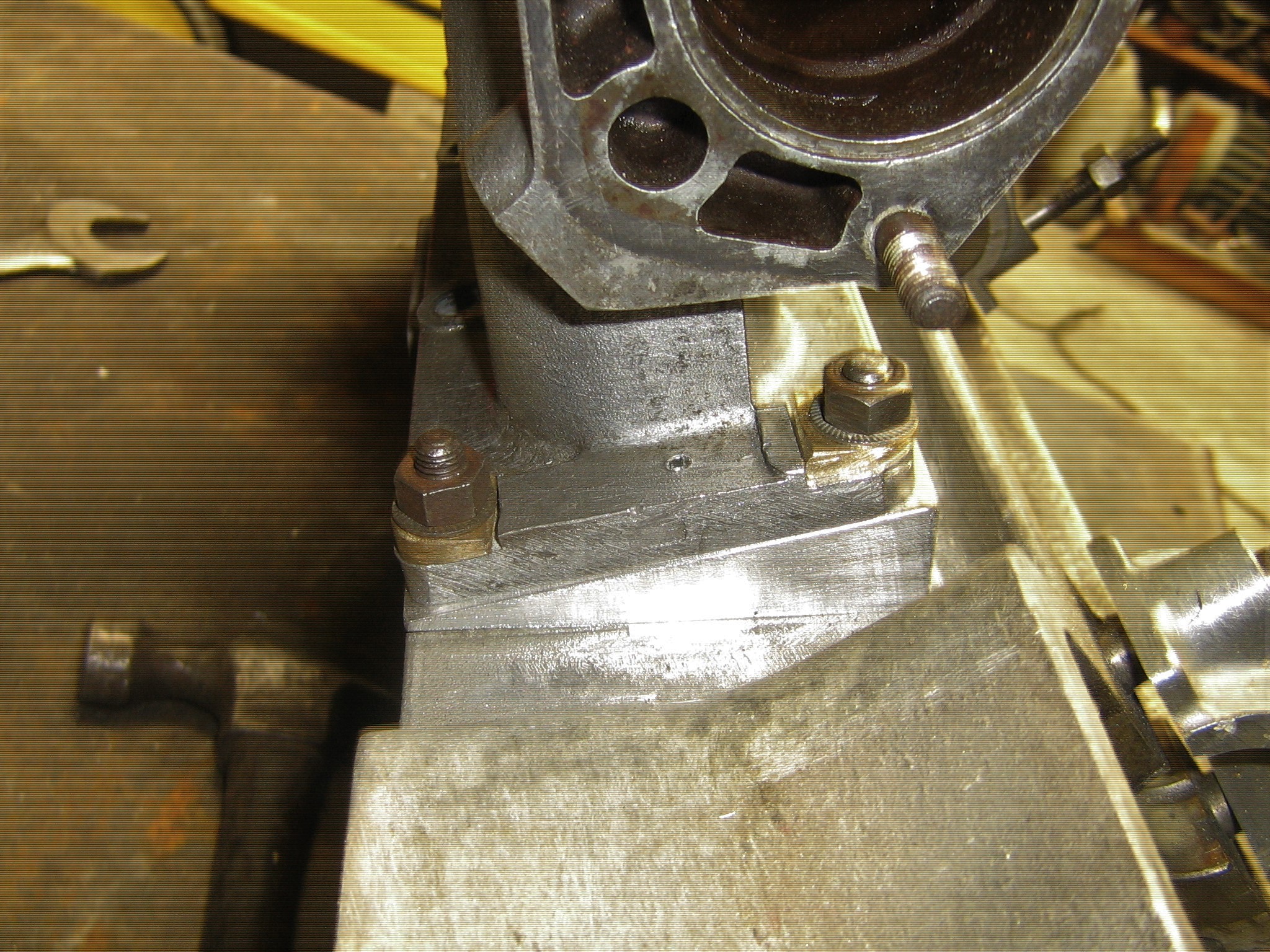
Roger photo as promised showing tapered D washers (in brass) to restore the correct
intrerface twixt nut and manifold. Manifold mounted on a spare head for the photo.
The adapter is dowled to the manifold to maintain port hole alignment.
BTW not a drop of Araldite used
Peter B.
“…straight port and everything else…”
D-types are different. Frontmost and rearmost pairs are moved forward and backwards respectively.
Thanks Peter. I am aware of tapered washers (of course) but still couldn’t envisage how you could accommodate a 10-degree spacer plate without oversize holes in plate to accommodate stud angle alignment, and then implications of accurate location/alignment of ports. So what did you do with the holes in the spacer plate and also the holes in the inlet manifold?
Roger
Roger the stud and port holes in the adapter plate, were bored with the material “in the flat”.
the angle then milled . Therefore the stud holes are at right angles to the joint face, adapter to
head, all the realignment is on the manifold… If the flange thickness on the manifold was say
3/4-1" realignment might cause a problem, but the flange thickness at the stud hole @ 11/32"
idoes not cause a problem in my opinion. As for alignment, adapter to head is straightforward,
provided the holes are bored correcly of course ! The adapter is then clamped to the manifold
making sure the port holes align, holes are then drilled to insert some locating dowles to avoid slippage while the stud holes are bored, with the adapter as a template.
The holes are bored with a end mill, a twist drill bit tending to "run off " due to the angle of course.
I can post some photos of the machining operations to clarify if needed.
When the manifold/carb assembly is built up I will post some shots showing an alternative to
the “cats cradle” of cables / linkages, employed by some posters, for starting purposes.
Take the last comment in the same spirit as myself Re the use of “Araldite”
Peter B
my brain is starting to hurt with this. whilst i very much appreciate the far greater knowledge, experience and intellect of fellow members i cannot understand how the transition takes place between the right angles thru the intake plate without some large clearance holes.
very much looking forward to the choke setup for the HS8’s
As was mentioned the holes are not drilled in the normal fashion but bored vertically to the face clamped to the head. A drill would wander down the slope whereas a end mill will hold its position.
https://images.app.goo.gl/bf9KQk5LWvXEeabPA
Phil, there is ovality introduced to the holes in the manifold but not to a great degree, believe me
I do not carry out this work just to see the manifold crack or whatever.
Re the Hs8s
Some posters , perhaps Robin is one, do not prefer the soleniod type starting carb, I for one do.
As long as the SC is controlled by a manual swich and the SC mixture is set correcly it is
a reliable device, after all it was fitted for over 30 yrs.
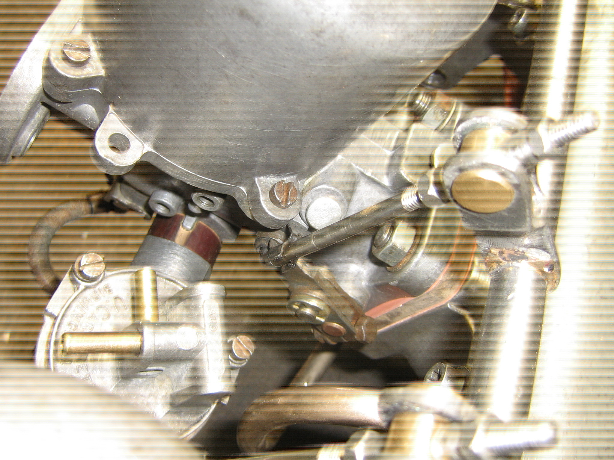
When converting MK2s to triple HD8s I detach the SC unit from the front carb, this is to rotate
the front float chamber 180 degrees, this helps with inner wing clearance.
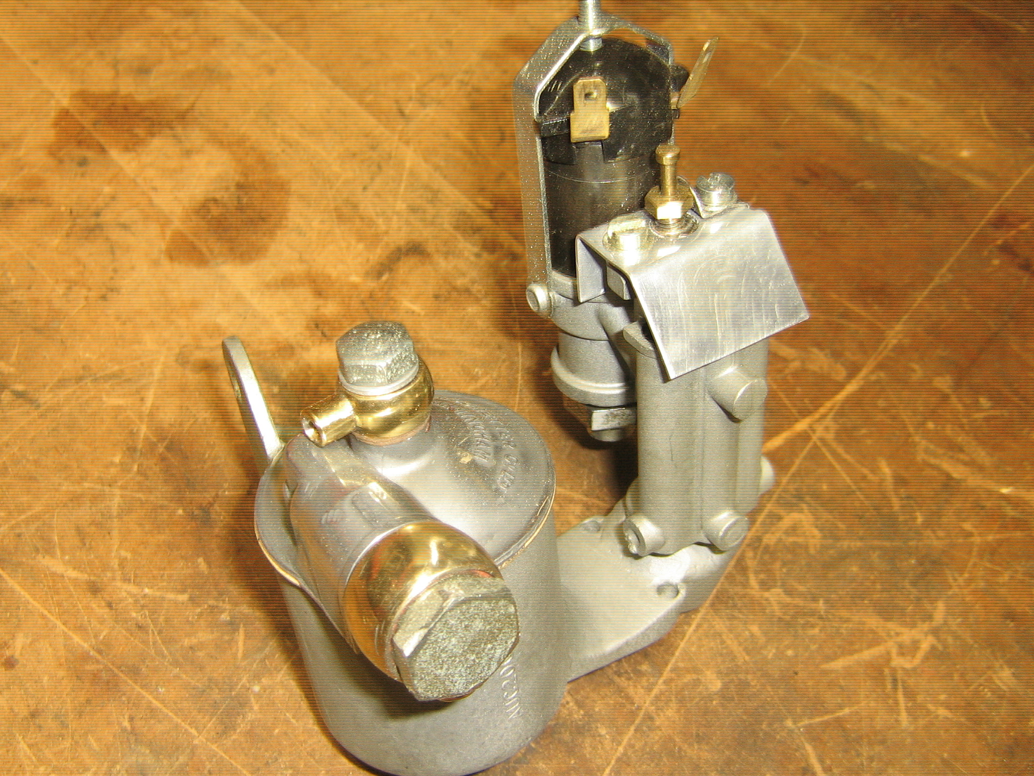
The SC is then wellded to a float chamber making it a self contained unit (photo) which for
a MK2 is fixed to the bulkhead and provided with a fuel supply. Connection to the manifold
is by Aeroquip style braided hose, for the HS8s this connection will be to the AED connection points. I have contacted the owner of a MK2 I converted some yrs ago who will post some fer you via me.
I prefer this method because I have a dislike for lowering and raising jets for starting purposes, in fact if I ran a E Type I would bin the standard linkage and fit this system.
For the 120 the installation is as shown.
Peter B
Got it! Thanks
With best regards
Philip Dobson