Appended are the fitting instructions for the SU fuel pump upgrade
SU Fuel pump upgrade instructions
Overview
The standard SU fuel pump uses a set of points to switch the pump on and off and the relatively high current of 3 amps passing through the points causes wear and tear on the switching surfaces. The upgrade uses the points to control a transistor which switches the pump directly, thus avoiding further wear and tear to the switching mechanism. (A transistor is “current multiplier” – when a small current flows through its base, it controls the flow of a much larger current between its other pins. This means the original points now only ever switch a tiny current to get the transistor to do the high current work, so the points do not arc any more and thus no further wear and tear occurs).
This is achieved by inserting printed circuit board over the bakelite assembly at the end of the pump and moving one of the pump connections onto a vacant hole on the circuit board.

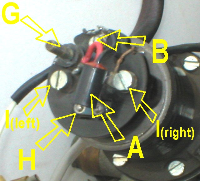
The suppressor A is removed and the pump connection at B is moved to B’ using a new brass bolt. The circuit board is inserted and B’ is kept insulated from the reconnected wiring using a spiral wrapped piece of sleeving at C. All of the other connections are put back as they were and the pump is ready to refit into the car.
The original suppressor is no longer needed as this job is done on the circuit board on the low current side, rather than directly on the high current side by the old method.
Before you start
Observe that the two coiled parts of the spring holding the end of the points cradle are above the line of the bar to which they are held. This ensures that the points remain spring loaded and move up and down to connect and disconnect the electrical circuit when the pump moves them.
Verify that the points do this by operating them using your finger on the adjustment bar.
This is so that you can be familiar with how it must move when it is reassembled.
Stripdown sequence
The pump has an insulating cap “D” which can be set aside and a rubber sleeve “F” which can be slid upwards onto the cap. The tag for the power connection, its nut and a star washer on the post at “E” should be taken off so that the large black plastic cap can be removed
The sequence of washers and nuts has to be removed from thick brass stud at G and set aside. When the screw at B is removed, the suppressor A can be removed and the blade H of the points will also come away. The blade contacts can be cleaned and the blade set aside. The suppressor will not be needed for the rebuild.
The two large silver screws and their washers I (left and right) can now be removed. The wiring from the points cradle underneath at I(right) will be put back in the same place during the during reassembly.
At this point, the bakelite assembly is held to the points cradle at its pivot and the entire end of the pump can be rotated 90’ to gain access to the underside of the bakelite assembly without removing the cradle’s pivot pin.
When you do this. You’ll notice that the cradle skips upward such that the two coiled parts of the spring (mentioned in the preamble) jump below the line of the bar. Don’t worry about this until the bakelite assembly needs to be lowered back again.
The stud at G has to be pressed out from above to allow the pump wiring connection onto G to be removed. Once this is done, the circuit board can be placed over the bakelite and with the pump connection eyelet over I(left), the stud at G can be pushed back in. The eyelet from G is now over the circuit board connection and connected to both the stud and circuit board instead of just being connected to the stud. Do not tighten any bolts yet.

With the circuit board over the top of the bakelite assembly, lift it slightly to allow the points blade to be replaced sandwiched between the bakelite and the back of the circuit board. Once the screw at B is replaced (finger tight), check that there is electrical continuity between the blade and the top of the circuit board where B attaches. To make sure that the circuit board is well lined up, use the two large silver screws I as guides and do not overtighten B. Viewed from the side, it should look thus:-
The second pump connection, the one with the smaller eyelet (marked J) can now be pulled underneath the board. Previously it connected above the bakelite at B, but it will now occupy the empty previously unused hole on the bakelite assembly. Because the wiring is short, it has to connect from below the board.
Even though the eyelet J is smaller than the one at G, in order to fit into the square channel recessed into the bakelite at L, the two edges shown as K need to be filed down slightly using a file so that the round eyelet is made smaller. (A spare solder tag is included with the upgrade in case you break the wire - otherwise no soldering is required to perform the upgrade.)
Use a brass bolt and a star washer to from below and press the trimmed eyelet into the recess. From above, a brass washer and brass nut secure the pump connection at L into the circuit board.
The bakelite assembly can now be pivoted back 90’ back onto the pump. When doing so, use a pointed instrument to jiggle the coiled parts of the cradle spring such that they are above the line of the bar as before.
The left hand I(left) silver screw and its washer can now be reattached.
The right hand silver screw at I(right), capped by the cradle eyelet connection and washer can also be done up. This connection needs to be kept isolated from the connection at L and a piece of spiral wrap insulation C is provided for this purpose.
The bolt at G has a spring washer and the brass nut concave surface points downards.
The insulation at C must stop the previously unshielded connection to I(right) from contacting L at the circuit board and at the eyelet below the board.
Verify all nuts and bolts are tightened up.
Check that the points still work by tapping on the adjustment bar with a finger. Verify that transistor sits above the line of the blade’s movement. So long as the bolt at B is done up, there should be no scope for excess travel of the blade. Check that the capacitor across the top of the points is also not touching the blade.
If all is well, reassemble the connecting components only onto G and test the pump.
It should rattle like a machine gun if fed with 12volts briefly and you should see the points moving up and down. (With no load and no sound insulation, it chatters faster than when plumbed into the car.)
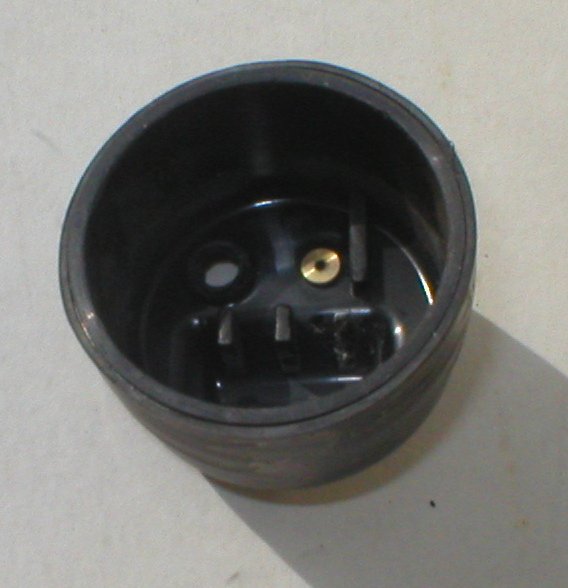
If all is well, the end cap will need one modification prior to final reassembly. The inside of the cap has three protruding lugs running down the centre line of the cap.
The lug marked M needs to be trimmed. To do this, use a pair of small pliers, grip it fully and twist several times. The plastic will come away and will look as below.
This ensures that the cap does not press down on the transistor which is sitting over the blade.
The soft washer can now be fitted to G. The cap should slide on and the star washer, Lucar terminal and brass nut can be tightened. The rubber sleeve can be slid back into place and the power connection reconnected. The pump can be replaced into the car.