So I have my carburetors all put back together and installed, put fuel in the fuel tank, cranked the engine and … nothing. All quiet from the fuel pump, so I removed that, and thought the piston seemed to be jammed. I opened everything up, but stupidly didn’t pay close attention when a small round metal piece fell out (see subject of red arrow in photo). It’s a newer version of the fuel pump, so all the how-to videos on the web show a very different internal structure. Anyone know where that piece goes?
Also, when I apply 12V to the fuel pump, I hear a single click. Is that expected, or should it be continuous?
A correctly operating pump will exhibit continuous clicking (pumping), the action of the points/throw over mechanism. The “click” rate should slow as the carb bowels fill (engine not running). Did you disassemble the entire pump? Did you unscrew/remove the pump diaphragm from the points? If so, did you follow the ROM re-assembly procedures paying close attention on points/diaphragm adjustment throw over? From your description (single click) it may be the pump diaphragm/points throw over mechanism is not properly adjusted.
Also, did you attempt to clean/dress the old points? Over time they oxidize causing problems. I’ve found it’s best to install new points rather that try to revive the old set!
Were you testing the pump as pictured - not mounted to the fuel chamber? It needs to be mounted to test properly.
Not sure what that small “washer?” is. Maybe someone with better knowledge can identify that part. Did it come from inside the points housing or the diaphragm end, if you noticed… Ha Ha.
It also would help if you identify what model/year car the pump is from.
Good luck in getting your pump sorted. They’re pretty simple but a PITA to adjust and reassemble.
Over the years I’ve rebuilt and/or replaced the points on many of these and I find that it is often trial and error to get the throwover mechanism correct.
John,
You’re soooooo correct. The ROM “usually” lays out the basics but a trial-and-error period is usually required! Fuel pump rebuild is pretty simple, you just have to get the throw-over adjustment correct or the “pump ain’t happy”!!!
Note: I’ve found procedures in the ROM are usually detailed for RHD vehicles unless noted otherwise. Thanks again Jaguar!!!
There are a series of those small washers around the margin of the diaphragm - one has fallen out. Take a look at this excellent video. It will also give you the proper setup for the throw-over mechanism and you will be back in business.
That small washer looks to me like it belongs on the brass stud electrical terminal. The 11 roller discs around the diaphragm are larger. Later versions have a plastic spider instead of the 11 roller discs.
Adjusting the flip-over contacts is trial and error, screwing the diaphragm shaft up and down until you get it right.
Then move the stationary contact into place over the moving contacts.
And of course some people like me go with a transistor modification or now there is a Hall Effect version.
Thanks for your replies. I shouldn’t have tossed out that question just before heading out of town. When I get back, I will post a picture of what the newer fuel pumps look like inside, as there is NO throwover mechanism now. Until I get back, please hold off on your great feedback until I provide more information.
The simple answer is you need to get enough deflection so the power is cut at the end of the stroke, by whatever is in place, points or sensor, and it may take a few tries but you should get in the ballpark easily.
It will pump air, faster if you hold the inlet, slower when you hold the outlet shut.
Diaphragm too far out (rod too long) leads to low volume or even open contacts all the time, too far in means the coil will never shut off and the plunger can’t return. The pump doesn’t pump at all then, just one click and then producing heat.
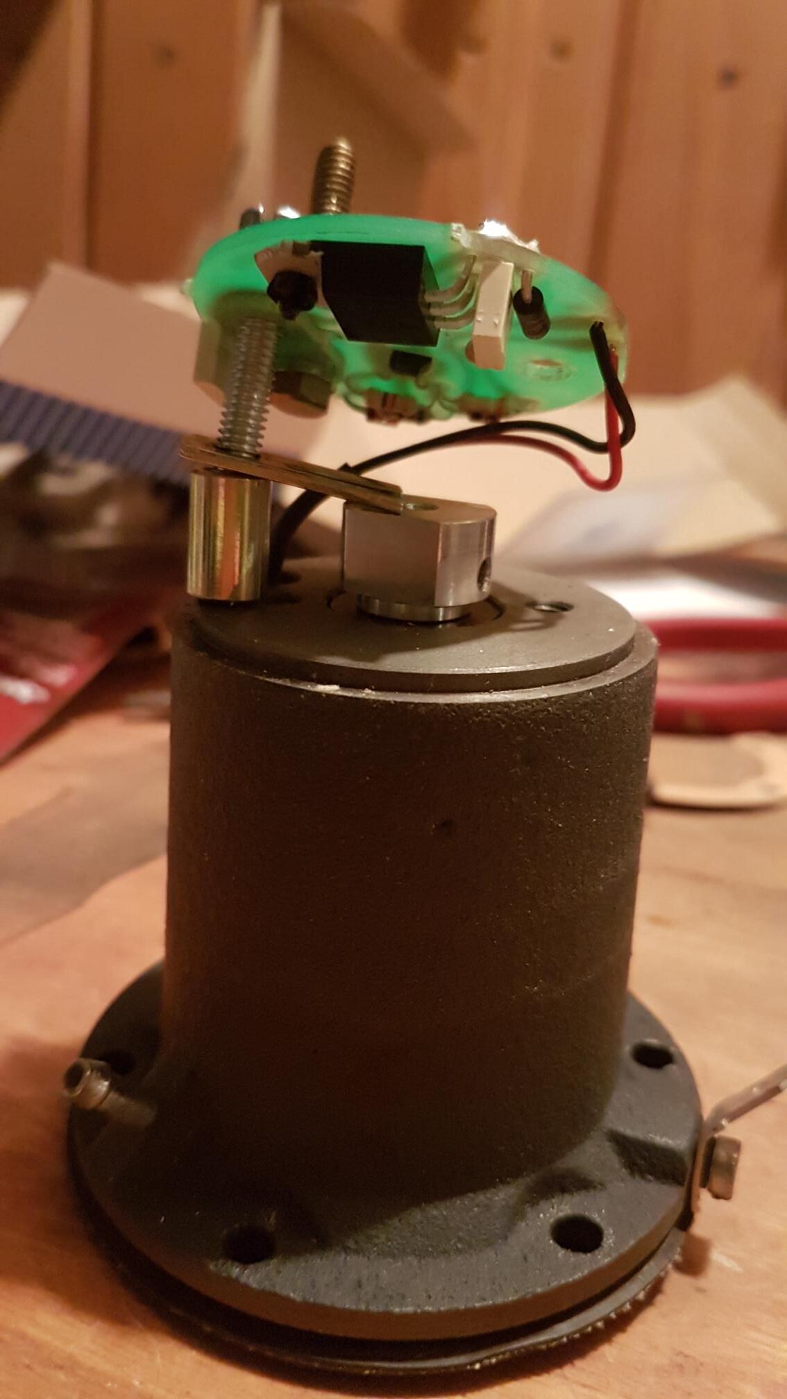
So here are 2 more views of the fuel pump. If I recall correctly, I bought it new from Burlen well over 5 years ago, so definitely not original. Even Burlen just sent me a PDF of the older style throwover-based pump in reply to my question. It’s being used on a '61 3.4 Mk 2.
Dick asked if I recall from which end of the pump the “washer” it came from, but as I hinted, it popped out when I wasn’t paying attention As you can see, though, from these photos, it’s too thick to be a washer. Yes, one of the photos suggests it’s an offset for one of the 2 posts, but if I add it to what looks like the shorter one, it’s too tall.
Rick,
Interesting first photo. Haven’t seen this type of electronic pump. Couple of questions:
First, is that a solenoid the diaphragm shaft screws into? Any wires coming out of the solenoid to the circuit board? That would explain the throw-over mechanism not being present. It’s using an electric pulse to operate something which makes the pumping action. With that setup you probably won’t have the ubiquitous “click” the the points throw-over mechanism makes. Are the Red and Black wires coil body wires? Again, the setup may be energizing the coil to actuate the diaphragm. That’s what the points did in the original design. This seems to replace the points with an electronic switch - WAG!!!
Can you provide some close-up’s of the top and side of the pump?
Have you reassembled the pump and tried it? If it doesn’t work my guess is there may be a bad component on the circuit board. I believe you can purchase a new board from Burlen. Other than that everything would be a WAG!!! Ha Ha
Electronic: It’s better BUT… Where do you plug in the OBDII?
Ok so you have a Hall Effect pump which switches on and off magnetically.
I still think that little washer is from the long brass wire terminal and popped off when you pulled off the cap. It was under the cap.
Rob, I tried it where you suggested, but then the cap didn’t fit snugly.
Dick, here are 3 more photos for you. Not sure what that thing is that the shaft screws into, but the tuning fork sits right above. There is definitely a single click when I apply 12V to the pump.
I think I figured out that washer/spacer. If the ‘washer’ I originally asked about is placed above the tuning fork (with the tuning fork sitting on top of the shorter post), and use the plastic and metal washer that I thought was for the main post (that sticks out of the body, which you can see in an earlier photo), the heights of the 2 posts match. I will reassemble and give it a try this week, and let you all know.
Thanks to all for your patience, and for suppressing what must be a strong urge to ridicule my inattentiveness!
I ran into an issue with this pump on the weekend.
I took it out and opened t up.
I was able to get it running again but the gap and position of the turning fork was hit and miss.
Are there any specs for the gap and fork location?
Thanks for picking up this very old thread; old thread but new issue for me.
I did dismantle it completely.
As for the correct number of turns, that is unknown, but may not be relevant. Or maybe it is and I am misunderstanding how this assembly works. That would not be the first time today.
Because it is a solid state type (no points) the threaded stem attached to the diaphragm simply slides through the solenoid and is secured at the “top” into the threaded magnet.
I am beginning to realize this is probably a conversion kit that was fitted to a points type pump.
Regardless, the assembly is different than the points version where you turn the diaphragm until the points don’t click over and then it is backed off one rotation.
In this assembly the rod from the diaphragm simply slide through the solenoid and is screwed into the magnet on the top. Then the tuning fork is rotated to whatever position that causes the rod to oscillate. So far to me it seems like a combination of how far the magnet is screwed on (and then secured in position on the rod with a set screw) and where the turning arm is located, which in turn is secured in place by tightening down the screw on the post.
Even a slight misalignment can cause the rod to stop oscillating.
I’ve been searching various forums etc. and the set up seems to be very elusive.


 As you can see, though, from these photos, it’s too thick to be a washer. Yes, one of the photos suggests it’s an offset for one of the 2 posts, but if I add it to what looks like the shorter one, it’s too tall.