For the C.840 Nut, Slotted, securing Flange, item U.2 on Plate U for the output flange, is there a commonly agreed torque? I’ve set the flange on the mainshaft to have the same remaining shaft exposed (0.35" until flange shaft expands in radius) past the oil seal as was found when I took it apart. The torque to get the nut to the next open slot for split pin fit was pretty trivial. I’m unsure on axial placement (how far the nut is threaded) of the flange and nut for best fit and prop shaft fit and also for the torque. It seems to me on the spares at hand that the nut is not drawn down to bottom the washer on the mainshaft spline end.
Hullo Roger,
I don’t know to what car you are referring but that may not matter too much as the technique is standard.
The flange should slide along the shaft and seat on the shoulder of the output shaft at the inner end of the splines without interference but with the feel of a bit of resistance. This is a precision parallel fit and ideally should have no slackness detectable by hand (albeit there is a micrometre of clearance to enable assembly). The outer end of the splines must be below the face of the flange to ensure the washer does not bear on the splines when the nut is tightened. The washer is a heavy gauge, not a thin gauge, as it needs to accommodate the high torque of the nut. The nut needs to be torqued to about the 120/130 ft lbs range, or the nearest split pin alignment that fits.
This is a high torque because of the shaft diameter and is essential to ensure the output shaft and the flange act as a single unit. If it is not tensioned adequately, the splines will start ‘working’ back and forth (hammering) and eventually wear a looseness in the splines and the washer. If it starts, it only gets worse. This is one of the critical engineering anti-rotational tension connections like rear axle hub nuts. I can explain the theory in more detail if preferred.
I hope this has helped.
This is a Mark V. The manual says nothing about torque on the rear mainshaft nut. I’ve always just tightened them down, then back off to the next slot to get the split cotter pin in.
1 Like
Unfortunately for some reason torque information in the early service manuals was not included and I can only assume it was provided to workshops by way of technical bulletins or similar. However it is important to ensure these are torqued correctly, not just what might feel tight.
I found the above reading in my S Type manual. I checked my Triumph 2500 manual and it states 100-110 for its 3/4" UNF shaft. The same torque is noted for its flange to axle shaft and rear hub nuts. If you try to undo nuts in these locations from a car that has not been dismantled or one that has been rebuilt correctly you will know the strength you need to release the tension.
Back then, ofttimes torque figures were not in workshop manuals: in the manuals for a PIII Rolls-Royce, they stated, “This should be accomplished by an experienced fitter.”
Your assessment of ~100 ft-lbs sounds about correct, for a splined shaft that size. If s torque chart does exist, I’m sure someone here will post it.
1 Like
This thread is directed to the SH and JH boxes, though I would say it applies to double helical, JL and OSL boxes as well.
Perhaps the torque spec applies only to later gearboxes with a regular hex nut and tab washer, not a slotted nut with split cotter pin.
I don’t see that a torque spec would have any meaning if you back off the nut anyway, to get the split cotter pin installed.
No torque spec in the Ball Autobooks, VanDiest or Chilton’s manuals either.

1 Like
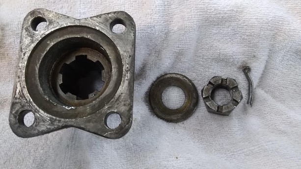
Here is what I have done so far, comments would be appreciated. The photo below shows the slotted nut installed and a slotted nut from a spare.
Note the slotted nut has 12 slots, as opposed to the more common 6. The total nut height is 8/16" and the unslotted height is 5/16". The threads are 12 tpi BS Fine and thus have about 3 1/2 threads in the unslotted height. I figure the 12 slots means the nut does not provide much axial force in the slotted thread portion. I’m reluctant to aim for 120 ft.-lbs on 3 1/2 threads. I got about 80 ft-lbs when a slot was just past split pin hole access, so I backed the nut about 5 degrees back and put in the split pin, as shown in photo.
What are people’s thoughts? Good to go?

1 Like
Yes, no need to risk distorting the threads, good to go.
I agree, this should be good. The twelve slots are intended to make it easier to get close to the desired torque without being too far under or over. Some shafts have two pin holes at 90° to achieve the same 30° steps. The modern approach is to use self locking nuts so that you can always set the right torque but you are only supposed to use them once. My method is to start at about 70/75 on the wrench, then going up 5 or 10 at a time, comparing each step with the pin hole position getting to the nearest hole under the specified torque.
As a related sideline, if you have conventional wire wheels with splined hubs, you may hear a slight click going from forward to reverse if the spinners are not tight enough. Continued use eventually ‘hammers’ the splines, but these wheels need a whole discussion subject of their own. The manufacturers don’t state a torque, I assume because there are too many variables in frictional resistance.