Can you broach gears?
Much the same method as myself, crossed my mind you might go with a metal spraying process.
Peter B
Yes.
Get them to send you a picture of the rear surface of the rear bearing (RMS 11) to ensure that the radius between the face and the bore of the inner race is minimal as shown in the picture of the bearing in a previous Post. KSM brand is the only bearing I’ve found to be satisfactory. The front bearing I use is a KSM RMS 13.
Regards,
Bill
Hello Peter,
I’ve had these journals built up using the Electroless Nickel plating. Its a particular process of Electroless Nickel plating called Nico Build developed for such applications where a reasonable thickness is required. The negative for me is that of the turn around; and the cost.
Regards,
Bill
Hello all and many thanks for all your comments.
If the RMS 11 is not right and conforming to your picture, I shall return it to SNG. But they told me they sell it for 30 years without any known issue.
Today, I built a rudimentary hexagonal spanner to remove the big nuts. I could easily remove the one on the first motion shaft but could not remove the one on the main shaft, although I exerted a very high torque. Hope it will be easier tomorrow after a good night with WD40! But if you faced the same issue, I would be intered by the solution you found. Apparently my gearbox was never dismounted from 1966…
Following Peter’s recommendation, I heated again the needle bearing race which remained inside the first motion shaft but could not remove it. And the metal is too thick and hard to pass a small screwdriver.
I hesitate to try to cut it with a thin grindstone and risk damaging the shaft’s surface.
Best regards.
Christophe
Hello Paul,
I turn the gear blanks on a CNC Turning Centre and send them to a specialist Gear Cutting company to have the gear form cut.
Regards,
Bill
Hello Christophe,
Most who work on their own Gearbox don’t generally look at the design and work out how the various assemblies work; they simply follow the instructions in a workshop manual to dismantle and reassemble the Gearbox. Most will measure the bearings or note the markings thereon and seek a replacement from a bearing supply outlet. Most working at such outlets will have never seen the correct bearing (pictured in an earlier Post) and with all sincerity, supply the bearing similar to the bearing you recently received as a direct replacement.
Once the Gearbox is back together and even with the bearing having minuscule contact with the Oil Pump Drive Sleeve, all will appear to be fine and in fact the Oil Pump will operate until the Drive Sleeve starts to slip, There is nothing to indicate whether the Oil Pump is working and therefore, the driver/owner of the car is oblivious to any looming issue.
The Oil Pump not working seldom causes a catastrophic failure of the gearbox and I would say the affect is accumulative. Many of the E Type Gearboxes I’ve worked on have come to me with the comment from the customer being “the last time I had the gearbox done up was 20 years ago” and they put the current requirement for work down to normal wear and tear. They forget the fact that the car gets driven only on a weekend and in that time, has not racked up all that many miles. Accordingly, I’m not surprised by the bearing supplier’s comment “selling for 30 years without any known issue”.
Jaguar at the time, would not have opted to use the correct configuration of bearing shown in my earlier Post for no reason. And the reason for the small corner radius is quite understandable.
Try and get a KSM brand, RMS11 bearing and that will do the job. As an added precaution when assembling the components aft of the rear bearing for the last time, I mask up all surfaces of the Oil Pump Drive Sleeve except for the face that abuts the face of the inner race of the rear bearing; this face is then abrasive blasted. After removing the masking and cleaning the Drive Sleeve, a small amount of LOCTITE - Retaining Compound is applied to the face of the rear bearing’s inner race and all parts aft of the rear bearing assembled.
Regards,
Bill
Good to know: that said, I don’t like Moss 'boxes that much to ever spend that kinda ching, making them right again!
Many thanks again, Bill, for your very valuable pieces of advice.
SNG told me they will send me a KSM RMS11 and I shall carefully check it corresponds to your earlier picture.
Thanks also for your recommendations for its mounting. I do not have a sand blaster bur will manage to get the drive sleeve surface a little rough and use some Loctite.
My main concerns today are to find ways to dismount the nut on the mainshaft and the remaining needle troller race inside the firts motion axle end ! For the nut, I shall try tgo heat it.
Kind regards.
Christophe
Hello Christophe,
Abrasive blasting will give a uniform texture without damaging the Sleeve, or changing it geometry (squareness of face to long axis) . The surface doesn’t have to be rough per se, just finely textured to hold a little of the LOCTITE. I would be reluctant to use any method that may damage the face in any way. If you have a very flat surface available, such as flat glass, you could create fine face grooves by placing a piece of, say, 180 grit Wet and Dry sandpaper (grit side up) on the glass, place the face of the Drive Sleeve on the sand paper and twist it just one or two rotations whilst applying downward pressure. This will produce scratches on the face without really altering the face geometry.
With regards to removing the outer case of the needle roller bearing left in the bore of the First Motion Shaft, you should be able to drive a sharp pointed tool with a long taper between the case and the bore of the shaft as Peter described. The bore of the shaft will be more unyielding than the Needle Roller Cup.
To get the case hot enough to shrink it, you will need to apply quite a lot of heat quickly and for a short duration. You don’t want to be putting any significant heat into the bore of the shaft.
It should not be required, but someone with a Cylindrical Grinder with an Internal Quill, could grind it out to within 0.0002" (0.005mm) of the bore. Actually, they wouldn’t have to go that close to the bore. At, say, 0.005" (0.127mm) wall thickness, the cup could be easily picket out with an “O” ring pick.
Regards,
Bill
1 Like
For the nut Christophe you might have resort to the Hammer chisel method,
You will not be the first ! or the last !
Peter B
Thanks again Bill and Peter.
I still tried to remove the nut with my rudimentary wrench and bent a square steel rod 14x14 mm (0.55" x 0.55") ! 
I am afraid of damaging the splines of the main shaft in my vice.
Regards.
Christophe
Basic advice I know Christophe, a piece of alu sheet on each vice jaw !!
Peter B.
Please test the fit of each new syncro ring. I had a bad one (4.2 full syncro) where the teeth were not machined deeply enough and they would not allow the ring to engage. Of course test the shift pattern before you bolt to the bell housing.
Comparing a ‘good’ new one to a ‘bad’ new one:

1 Like
Thank you very much Peter and Mitchell .
It’s incredible that bad synchro rings may be sold. I shall check when I receive mine. Thanks for the warning.
Best regards.
Christophe
Hello Christophe,
14mm square will bend reasonably easily if its mild steel. You really need something where you can use a breaker bar, or the like.
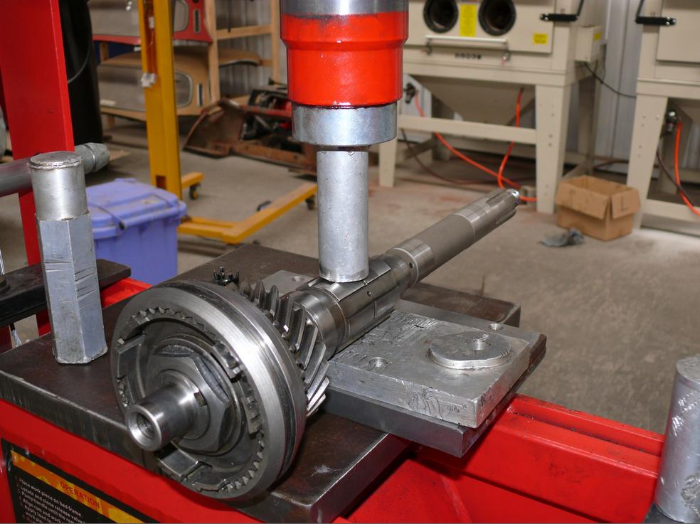
As pointed out by Peter, aluminum will protect the spline of the Main Shaft. By arranging the cut outs of the spline against the jaws, rotation of the Main Shaft will be inherently resisted. The arrangement of the Main Shaft in my set up is shown in the following picture:
In this set up there is actually very little pressure being exerted by the press. A fair amount of torque can be applied as shown with the following:
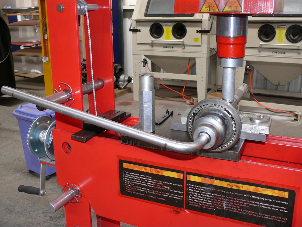
and as Archimedes reportedly quoted “Give me a place to stand, and a lever long enough, and I will move the world.”, the following will overcome the tightest of nuts.
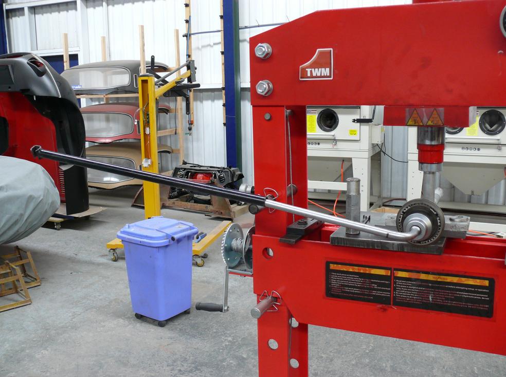
If you can’t arrange a strong lever, a high powered Impact Driver (if you can access one) is excellent for undoing really tight, threaded fasteners.
Regards,
Bill
1 Like
Thank you very much Bill.
This set up is really impressive.
I shall reinforce my lever.
Regards.
Christophe
Hello Jack and all.
Could you, please, give me the reference of the Bentley manual ?
I did not yet find it on the net.
I found, in addition to the Haynes I already have:
- the JAGUAR E TYPE MODELS 3.8 & 4.2 LITRE SERIES 1 & 2 SERVICE MANUAL: Workshop Manual by Brooklands
- the E-Type Jaguar Restoration Manual by D. Barzilay
- the E-type Jaguar DIY Restoration & Maintenance: A Kind of Loving by C. Rooke
Do you know and would you recommend them ?
Best regards.
Christophe.
Christophe,
The Bentley is a reprint of the factory workshop manual, and it looks like you may have that already by Brooklands. Do a search for “Complete Official Jaguar E Type Workshop Manual”.
Thank you Jack.
Christophe