That’s impressive: do you have your own machine shop and hardening facility?
Hello Paul,
A fairly well equipped machine shop with two CNC lathes, one a Sliding Head, Swiss style with live tools, the other a conventional Turning Centre and two CNC Vertical Machining Centres with pallet changers. I send the parts out for Heat Treatment in a controlled atmosphere. Making Ball Pins and Cups, holding tight tolerances, is not a difficult task using CNC Turning Centres and the reason I find it gob-smacking that many of the manufacturers of these parts get it so wrong.
One job I have for the Machining Centres is the machining of the aluminum housing that the pinion tower for an S3 Power Assisted Steering unit attaches to. This is the only part of the Rack Tube that is not ambidextrous.
Regards,
Bill
Do I see the plastic sleeve over the taper? That is a no-no. You want the taper to be steel on steel.
Yes. Even using a valve spring compressor I couldn’t get it to go. I finally sent it back and reused the one in there since PO had included a receipt indicating replacement of BJ’s and it seemed ok. I originally ordered the kit because it was going to be the same amount of work to reinstall old vs new. Surprise!
The original part (replaced in the After Market kits with plastic top hat component being discussed) is a rubber sleeve. It should sit in the undercut between the top of the Taper and the start of the Ball Pin spherical surface. The small ID of the Gaiter then locates on the surface of the rubber sleeve.
Regards,
Bill
I installed this top hat as suggested, brim on the threaded side. This brought the brim right around where the old ball joint has a groove machined on the taper for the seal. So that looked good and made sense. Unfortunately when I tried to finish the install I found that like Bill Bilotti, I could not get the circlip in the groove, even without the spring or the shims. So this is going back. Lots of wasted time on this.
John North
S1 Roadster
SNG must have had a lot of problems with these. They’re sending me two more and told me to pitch the ones I’ve been working on which is good service. I ordered them in July so if you have some on the shelf wating for installation, send them back…
John
Hello John,
Anyone that has been involved with CNC machining for a while can look at a part and tell if its been machined using a CNC machine tool; the Ball Pin and Cup certainly is.
OD machining is the easiest to keep in tolerance, particularly compared to bores that are long relative to their diameter. Back in the early 1980’s I designed and manufactured a single shot target rifle (Google Angel M80) and held a tolerance for the main bore of the action (19.0mm diameter x 206.0mm long) of +0.0 to -0.01mm (+0.0 to - 0.0004") for runs o 100 parts in 4140. The only reason to change cutting tools at that point was that the surface finish of the bore just started to drop off, but the bore diameter was still within tolerance.
The OD turning on the Bolt Head (close running fit in the main bore of the action), not that it was required, but a tolerance range of 0.005mm (0.0002") was held over a couple of days without changing the cutting insert. The operator of the machine was a “week into it” apprentice under strict instruction.
CNC machines can make very accurate parts over relatively long runs, very consistently with minimal interference. They can also make great looking rubbish parts with the same amount of ease; it just comes down to the management of production. Parts such as Ball Pins and Cups are very easy parts to make (and hold tight tolerances) on a CNC Turning Centre and an absolute stroll in the part compared to the Rifle Action parts described. A check on the parts being in tolerance can be made without any loss of production time by measuring the last part made whilst the next is being machined. Its good practice to have separate Roughing and Finishing tools and therefore, provided the in or out of tolerance of the part determination is made before the Finishing operation on the part being machined, then remedial action such as changing a tool Offset, or the cutting insert can be made without loss of the part currently being machined.
Based on many parts I’ve seen being supplied by the usuals, that are clearly CNC machined, the people making these parts are either absolute amateurs, or just don’t give a toss.
Regards,
Bill
The “top hat” goes down so tat it seals on the Gaiter
John North
S1 Roadster
[/quote]
this is the replacement bj I could not make fit:
Is this the same? Cause I couldn’t get the top fitted, even with no shims IIRC.
[/quote]
Bill, the Kit you show here suits both 3.8 and the later wishbones. The 3.8 wishbone was machined differently, as it used a rubber Gaiter on the large plastic ring. It is also possible that the ball cup has more material to allow for ball seat wear so that you may have to machine/grind off to get it to fit.
Hello Norman,
If that were the case, the manufacturers are supplying them with random amounts of more material, based on my observation of measurements.
All workshop manuals for the E Type and memos from Jaguar on the subject, state that excessive wear should not be compensated for by shimming and that a new part (wishbone) should be fitted. Having added thickness between the spherical surface and the flat, top surface of the Ball Cup is tantamount to the addition of extra shims.
If a tolerable amount of wear is to be taken up, would it not be far more sensible for the manufacture/supplier of these kits to supply additional shims, rather than a Ball Cup that requires machining? To machine this part correctly, either a surface grinder, or Hard Turning facility would be required. Replacing the Top Ball Joint assembly is a job that all mechanics and DIY practitioners should be able to do and many of them won’t have the equipment to machine the cup correctly.
I very much doubt that its a case of the manufacturer thoughtfully supplying the Ball Cups with extra thickness to take up wear, but just pain old shite manufacture. The randomness of sizes of both the Ball Pins and Ball Cups I’ve observed indicates shoddy machining, and not added material by design.
Regards,
Bill
Yes Bill, you are right on both counts.
Jaguar say the wishbone should be replaced when excess wear occurs, but what an expensive way of doing it.
And some of the Ball kits supplied these days are not of best quality.
I have “resized” the ball cup using a belt sander without any problem.
Also I have also offered rebuilt exchange wishbones for the last 40+ years, where I weld up the ball seat and re machine it, at the same time adding more seat area that has a bronze coating to provide for a longer life.
Hello Norman,
Yes, it would be an expensive method of resolve and I also repair existing units. I was making the point that any responsible manufacturer of these kits shouldn’t be supplying an over lengthened Ball Cup to compensate for excessive wear. If the Ball Cup is over lengthened by an amount that prohibits the components being assembled with all shims omitted in a wishbone that is not so worn, in my book, that’s compensating for excessive wear if the assembly can be put together with over lengthened Ball Cup as is.
With regards to using a belt sander to resize the ball cup, exaggerating the results for the sake of discussion, you could end up with the top surface at an angle substantially off of the correct 90degs to the Cup’s longitudinal axis and it would seem to assemble without a problem; but it is not correct. Further, why should you have to resize this part? Its like having a dog and barking for it, when you pay considerable money for these parts and then have to fix the stuff ups of the manufacturer.
The upper wishbone is a relatively unstressed part and the chances of it failing catastrophically are slim. However, any repair where heat to the extent that the characteristics of the metal may be changed is leaving oneself wide open to litigation. The material used in this part is a high carbon, through hardening steel and incorrect management of the heating process could lead to the area being too hard (brittle).
I used to reclaim excessively worn parts by building the worn area up using like material filler rod, machine the area to the same size and tolerance as specified by an original drawing and induction, surface harden the ball seat area using a custom made induction heating element, to the same heat treatment specification as the original. It was an expensive process and I no longer use this method.
With many of the shoddy parts being supplied, I believe its often the case that the end user fixes the part, as in your example with the belt sander, and the manufacturer doesn’t have to worry about it; where’s the incentive for the manufacturer to make good parts in that scenario? If more parts were returned, maybe they would get it, that they can’t sell crap and they need to improve; its not like these parts are being given away. Where Ball Pins, or Ball Cups are machined using a CNC Turning Centre, there is no excuse for either of these parts being made out of tolerance of the original part dimensions, other than total lack of manufacturing ability, or sheer laziness.
Regards,
Bill
Bill, I’ve been repairing E’s for more than 50 years, and yes the wishbone is a low stress item.
Have repaired many accident damaged ones over the years using correct heating and cooling procedures that were approved by my Insurance Company.
Building up of the ball seat by welding and layering the seat with bronze does not affect the integrity of the wishbone in any way, the bronze is a relative low heat process, the same process used for construction of the Chrome Moly tubing engine frames.
Using a belt sander is not a problem if you know what you are doing and was only used to remove a few thou in most instances.
Obviously you would machine it if a large amount was required to be removed.
Item 11 was introduced by Jaguar for the S2. It followed into the SIII. It is made of rubber and slides over the taper to fill the gap between the taper and the ball. I assume it was to keep crud from accumulating in the gap or provide a soft landing for the cup when the load was taken off and the wheel dropped down. Other than this all components for the upper ball joint for the S1, S2 & S3 are the same. Item 11 is not available and as I recall it has not been available for a very long time. The goofy top hat piece I have seen before and assumed it somehow was a substitute for item 11 but I never could fit it. Then I figured it had been placed over the ball pin threads to protect them while the kits were being shipped. Who knows. Bottom line is you don’t need item 11 according to the original S1 configuration, which worked fine, and the top hat piece is not original.
Richard Liggitt
Norman,
I think you’re missing the point. Nothing beats not having to resize the Ball Cup irrespective of what method is used. The notion that “It is also possible that the ball cup has more material to allow for ball seat wear” implying that its a design feature orchestrated by the manufacturer is laughable, particularly when you measure a few and see how variable they are dimension wise.
I reiterate, why should you have to resize the length of the Ball Cup to enable assemble, when it would have been a whole lot more convenient for the end user, and no harder for the manufacturer to have made the parts the correct size. A tolerance spread of 0.01mm (0.0004") is relatively easy to maintain on a CNC Turning Centre with parts like the Ball Pin and Cup being discussed and as there is no real need for the tolerance to be quite that tight, these parts are supper easy to get right, but extraordinarily, it seems beyond the capability of whomever is making them.
Things have moved on in the last 50 years, and where is was allowable and common place for chassis members of cars to be heated in the process of collision damage repair, its no longer allowed; at least not here in Australia. I doubt that you would get any insurance company approving the heating of a suspension component nowadays.
Comparing the suspension wishbone with an engine frame is tantamount to comparing an apple and an orange; the material used in each are poles apart. Depositing bronze filler rod on the surface of the Ball Socket requires a temperature of around 900°C. The temperature to harden Carbon Steel is usually between 800-900°C and tempering at a much lower temperature. Clearly, the temperature required for brazing will have an effect and it will depends on how the part is cooled as to whether its detrimental or not.
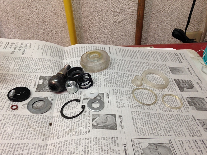
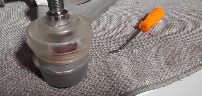
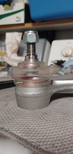
Just finished my upper ball joints this weekend. Not saying it is the way it should be done, just the way I did it. Here are a couple of photos of how I did it for anyone that has trouble in the future. The top hat will stretch over the taper with a bit of force after heating in very hot water. Took a couple of attempts but eventually seats on the ridge at the bottom of the taper. The hard plastic ring with the U profile fit’s in the recess and then the boot fits into the U. The small bent pick from Harbor Freight works great for stretching the boot in place (also good for caliper seals). I decided to use twisted wire for retaining the bottom of the boot in place as the hard plastic ring was a pain, the twisted wire is way easier.
I also had the issue where I could not compress the top enough to insert the circlip with the spring in place. It appeared to me that the new spring was slightly thicker than the original and the top not totally flat so I think it was moving to the side under compression and snagging on somewhere. I ended up using the original springs and did not have this problem with them.
Jay
Just received the upper ball joint kit RTC2203 and included is the said plastic top hat. Am I missing the drift here? If it’s fitted as Jay illustrates in the photographs
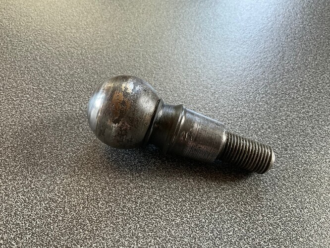
then it would squash inside of the taper which should be metal to metal if I’m not mistaken. Please enlighten me as I’ve read through numerous topics on this subject and and I am none the wiser. The old ball pin had a black rubber sleeve at the base of the ball as shown in photograph.
The top hat needs to slide all the way onto the pin past the taper, as per your original pins. Installing only part way may work in that it will probably be forced upwards when you try to seat the taper, But I’d be inclined to install it correctly from the start. There are black rubber grease boots out there that don’t use the top hat. I installed them during my last front end refresh, but don’t recall where I purchased them.
Hi Steve, I can’t see that, as in the photograph from Jay it only appears on the taper itself and not stretch up to the ball which would act as a sandwich filler in the taper.


