Hello, I just wanted to share my experience with rebuilding the upper ball joints on my 1970 FHC.
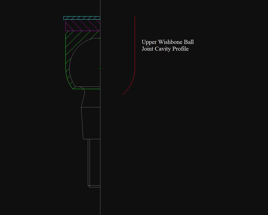
Someone prior to me had assembled them with shims with a center hole that would not clear the spring outside diameter. They came apart that way and due to a lack of information, I reassembled them as they had come apart. The shims in the rebuild kit had a larger inside diameter than those I removed, but still not enough to clear the spring. This created a situation where the shims compressed the spring the distance of the shim thickness. Now I determined the inner shim diameter should clear the outer diameter of the spring. This allows the setting of the 0.004 inch (0.01 mm) clearance of the upper ball socket as per the specification in the shop manuals. (Both factory and Bentley.) After this clearance is set, install the spring contacting only the upper ball socket and the top cover. I found the circlip in the aftermarket kit was a smaller outside diameter than the groove in the A-arm and fit loosely. When I separated the upper joint from the stub axle carrier, the circlip failed and the inner parts went flying. Found them all. The original circlips were a snug fit and I reused them.
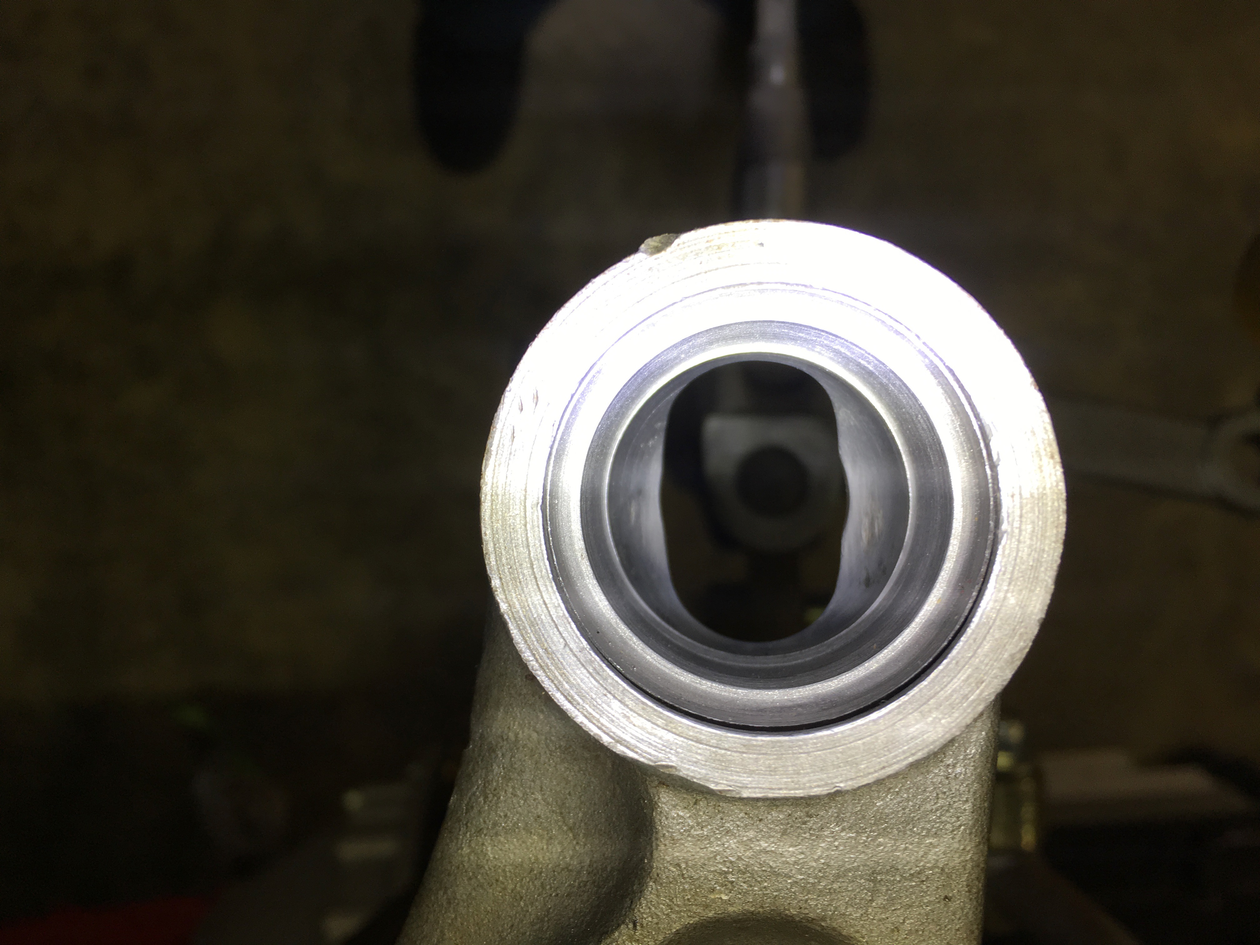
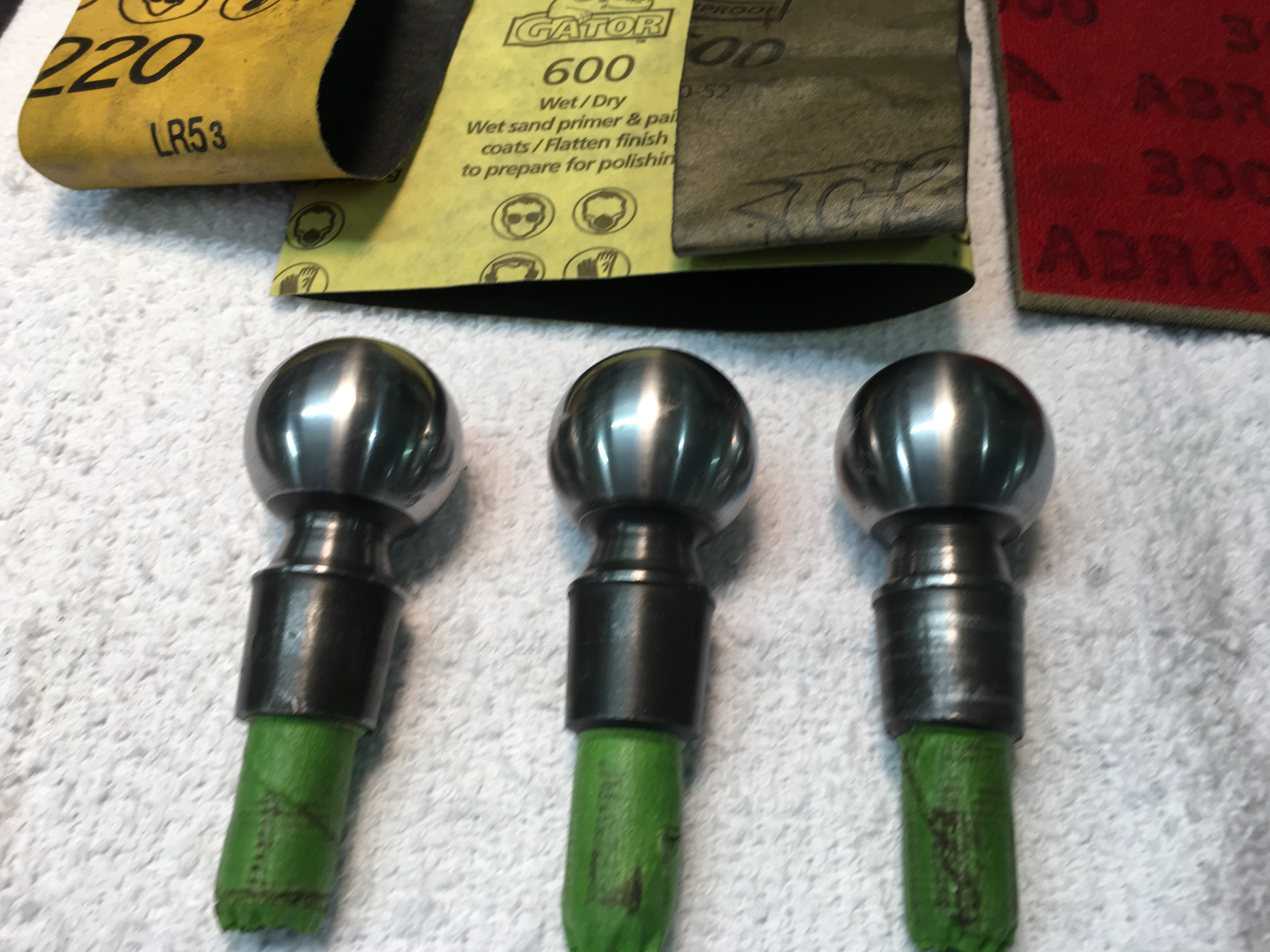
Here is what I did to prep the A-arm socket and the ball pins. The socket in the A-arm had minor galling due to lack of lubrication. I polished out the high spots using wet dry sandpaper: 220, 320, 600, 1500, finishing up with 3000 grit. I polished the ball pins in the same manner. I could no longer detect any high spots and any small pits will hold a little grease.
As per the manual I assembled the joint without the spring, shimming until it was tight. I then swapped out the shims and top covers until I arrived at the 0.004 in clearance.I found the top covers to vary in thickness from 0.074 to 0.081 inch. the final movement feels good to me. It happens that 0.004 inch is the valve clearance of many of the air cooled VWs I have had in the past, after a while you develop a feel for that slight clearance.
The greatest amount of time was spent determining how the joints go together. I am waiting on some shims I hope are correct. If not, I will clearance the shims I have to clear the springs.
The images show before and after of the A-arm sockets and ball pins. I hope this helps.
Keep smiling,
Mike
Hello, I just wanted to share my experience with rebuilding the upper ball joints on my 1970 FHC.
Someone prior to me had assembled them with shims with a center hole that would not clear the spring outside diameter. They came apart that way and due to a lack of information, I reassembled them as they had come apart. The shims in the rebuild kit had a larger inside diameter than those I removed, but still not enough to clear the spring. This created a situation where the shims compressed the spring the distance of the shim thickness. Now I determined the inner shim diameter should clear the outer diameter of the spring. This allows the setting of the 0.004 inch (0.01 mm) clearance of the upper ball socket as per the specification in the shop manuals. (Both factory and Bentley.) After this clearance is set, install the spring contacting only the upper ball socket and the top cover. I found the circlip in the aftermarket kit was a smaller outside diameter than the groove in the A-arm and fit loosely. When I separated the upper joint from the stub axle carrier, the circle failed and the inner parts went flying. Found them all. The original circlips were a snug fit and I reused them.
Here is what I did to prep the A-arm socket and the ball pins. The socket in the A-arm had minor galling due to lack of lubrication. I polished out the high spots using wet dry sandpaper: 220, 320, 600, 1500, finishing up with 3000 grit. I polished the ball pins in the same manner. I could no longer detect any high spots and any small pits will hold a little grease.
As per the manual I assembled the joint without the spring, shimming until it was tight. I then swapped out the shims and top covers until I arrived at the 0.004 in clearance.I found the top covers to vary in thickness from 0.074 to 0.081 inch. the final movement feels good to me. It happens that 0.004 inch is the valve clearance of many of the air cooled VWs I have had in the past, after a while you develop a feel for that slight clearance.
The greatest amount of time was spent determining how the joints go together. I am waiting on some shims I hope are correct. If not, I will clearance the shims I have to clear the springs.
The images show before and after of the A-arm sockets and ball pins. I hope this helps.
Keep smiling,
Mike


 Hope to be on the road this year.