When an apprentice learns a trade it is usually from a master. I am not even an apprentice but some of ya’all have done this kinda thing before so looking to ya for advice.
I have checked clearances thrice and recorded the gap. I am now removing the cams. The bolts are out of the gear and on the exhaust side all the bearing caps are off carefully placed in the exact position removed. Now it is time to lift the cam out so I can get to the followers.
How does the gear with timing change remove from the camshaft? I’m guessing loosen the tensioner? And how to lift the cam out of its position without damaging it?
Do we understand your task is to change some adjusting pads in the valve tappets?
Turn the crank so the cam alignment slots are in the standard alignment position.
Don’t turn the crank again until you are all done.
Remove the breather cover. The top timing chain is loosened by first slackening the lock nut there, then pushing in the little locking plunger and turning the serrated plate.
The picture in the manual shows the tool they used at the factory, but parts vendors sell a different type. Or a pair of long nose pliers will work.
Then with the chain loose and the two bolts out you can pop the chain sprocket off the end of the cam shaft with a light hammer.
If you don’t turn the crank everything should go back together easily.
Now you can loosen the cam bearing cap nuts a little at a time. The valve springs will push the cam shaft up.
The cam bearing caps and the head positions are numbered.
Any time you are working around the open front timing area, stuff a rag down in there to catch any nuts, washers or sockets that may drop, so they won’t fall down in there.
IF you engine is old enough, you can thread a couple of exhaust nuts…or…3/8", fine thread nuts…on to the centralized cam plate pin once you have withdrawn the sprockets from the cams…everything will stay in place that way.l
Later engines had a pin with a groove to help with wiring then in place.
Short answer yes that is the task at hand. But hold on… you say do not turn the engine? I had to in order to gain access to the 2 bolts on the cam gear. So sorry had to turn engine.
Knowing this, I presume you are saying now is the time to find TDC and at this point do not turn the engine so everything will line up. If so, I’m okay.
Now I need to lift the cams to get to the adjusting pads to mic them for replacement.
How does the gear at the #6 end of the engine separate so the cam will come out to do that work?
It’s been a long time since I did this. I thought that with the cam positioned with the notch as in the picture, there was access to the two bolts. Maybe I’m wrong. I may have to start admitting to senior moments.
With the two bolts out, tap the sprocket with a hammer and it will come off the camshaft.
With an off set wrench I was able to remove both bolts without turning the engine. Doesn’t matter since she will still be returning to TDC. The dizzy will be off by 180 degrees, though.
Probably easier to set engine with cam slots facing down, remove accessible bolt, then turn engine one revolution and remove other bolt…ending up with TDC AND cam slots up.
I retraced my steps a d find I have messed up in a big way. I thought to check the TDC by using the rubber stopper in #6.I turned the engine over with no stopper popping out. Then I realize the intake side cam isn’t turning because I had forgotten I had already removed the 2 bolts. I did attempt to put the bolt back in but the alignment is just off enough to not line up.
Ok it can be fixed. If the chain has not jumped any teeth and the exhaust cam still has its two bolts in, just back up to where the notch is at the mid position, and you should be at TDC or close enough.
Another way to find TDC is with a long screwdriver or anything long enough to reach the piston top, then turn the crank and watch it reach top position.
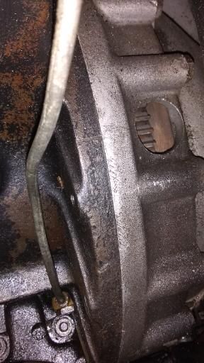
The TDC mark is an arrow visible through this hole in the bell housing.
I forgot and Lee is right that you get one bolt out first, then turn the crank until the notch is at mid position and you can get the other bolt out.
Now you can remove the cams.
From that point don’t turn the crank.
Sounds like the cam is only “off” by a tiny bit…you can turn the cam slightly to get the bolts lined up again as long as there were no other misalignments or tooth jumping, as Rob mentioned. You may be able to slacken the adjuster more, which will give you some extra slack.
Ah, then you’re probably better off removing the radiator.
Then while that’s out of the way, you can look at the front mounts, water pump, tie rod… welcome to shipwright’s disease.
WHOA !!
THIS IS WHAT Maddy said: retraced my steps and find I have messed up in a big way. I thought to check the TDC by using the rubber stopper in #6.I turned the engine over with no stopper popping out. Then I realize the intake side cam isn’t turning because I had forgotten I had already removed the 2 bolts. I did attempt to put the bolt back in but the alignment is just off enough to not line up.
Any way to fix this?
MARIANNE DAWSON
so.this sounds like the intake cam was in place…caps still on…but the 2 front sprocket bolts removed…now IF the bolts were removed.(and it seems you did this step? :“with the chain loose and the two bolts out you can pop the chain sprocket off the end of the cam shaft with a light hammer” so that the cam was then disconnected from the sprocket/chain drive)… .AND the intake cam was in place but not moving…any turning of the engine via the crank bolt (or other means) would move the pistons…but NOT the intake cam…and that is not good…hope the engine turn movement was tiny…not all the way around…valve to piston contact would occur. Not sure why looking for compression on #6…as that was already set up…when you had the front cam lobes pointed outward, and the cam alignment notches already lined up. Maddy, you said the cam bearing caps are OFF on the exhaust side…how bout intake side…? For me…I need to better understand the steps taken so far…and the current state/position of “things”…the cams, caps, sprockets…and DID you when all was at TDC #6 Compression…make a paint daub mark on the flywheel tooth and bellhousing to indicate TDC 6 Comp? (for the forum there was no mark…so one needed to be made)…IF you did…is it still lined up?
Nick
and this… oops…I have to think that situation thru…let’s share all with the forum … you already have the Paul Saltwick…article on Valve Adjustment …and there is another article by Pat Harmon…but my document combines and adds details to help clarify and stress some important tasks and steps… So I need to understand…where you are now…see if correct…You had the engine at TDC #6 (front most) on compression…front valve lobes pointed outward both intake an exhaust, and the cam timing notches lined up…right? SFSG…(So Far So Good). Did you then…with the front breather cover removed…attempt to or actually do…tighten the timing chain via the adjuster with use of the special timing chain adjuster tool? if you did…a small tighten of the chain may not have moved the cams…they remain aligned at the notches (cam timing tool)…OR…it may have moved the cams a little…if they moved…not it is only the cams that moved…the crank pistons did NOT move…so the engine is still at TDC #6 compression…as it was…so if the cams moved a little…the cams need to be re-aligned to the notches…a small move…but necessary…this is done by the cam end sprocket serrated plate for each cam…re-align using the cam timing tool to the notches…the cams MUST be aligned at the notches…to proceed to next steps. so the next step then…is to look at the two cam sprocket bolts…2 on each cam…one will be accessible, one will not (each side)…you will want to get to the inaccessible one FIRST…so to do that you have to make it accessible…rotate the engine in the normal CCW (from position of driver) or clockwise looking at the front crank)…just enough to get to what was the inaccessible bolt…each side will become accessible at the same time…so…remove that one now. Now…when both sides have that one bolt out…rotate the engine back to where it was…and just a little more…so that then stop…and rotate back in proper direction to align cam notches…this ensures cam timing chains have moved in the way they should…taken up any slack…and there always is some…so the final rotate should be in proper engine rotation direction…not the tiny back rotate you did… (so after first bolt is removed, you just come back…and not all the way around…just the reverse rotation of what you had done)…so that the remaining bolt is now accessible again…go just a little further…now rotate back in proper operation direction…so that the cam timing marks are lined up again…and that remaining bolt is accessible. Just as it was before you started…great…cams lined up again at notches and last bolt again is accessible. Double check–cam notches aligned…fine…remove the second-final bolt…
so if I understand…you removed the second bolt…with the cam notches not quite aligned at the notch marks via the cam notch timing tool…hoping since then…since both bolts removed…the engine has NOT been turned at all…if crank not turned…whew…OK…Did you remove cams yet tho? If not…just reinstall the one bolt on each cam that is accessible…it should still be where you left it…if not exactly.only a hair off…you want to get that one bolt each side back in…when that one bolt…each cam side is in…then you can rotate the engine the tiny bit back to align the cam notches exactly…that one bolt should now still be accessible to remove…both cams now at the notch alignments…Let me know…whats up…after you think this thru…and your looking at it…so I know whats up…Nick
While the timing chain adjuster tool should fit…between radiator and engine to fit into the holes in the serrated plate…it is tight…and difficult to get the tool lined up so it simultaneously released the catch plunger off of the serrated plate. Radiator out…certainly a task but easier for the adjust…and maybe a good idea anyway…to get to other stuff…and to have the radiator checked at “Corkys” in Spokane.
Nick
More for Maddy: first…important maybe—try to ascertain as you take shims carefully out…which side of the shim was on the stem…it is entirely possible that in prior work…someone already put the dimpled side inward toward the inside of the follower, …you may need to know that…if a thousandth different…I will come back to that…, so ahh a timing reference line up mark on the block…(and not on the bell housing) I have heard of that…so now to see if there is a mark on the flywheel…should be visible…since you are at TDC #6 compression…but…if not found due to rust etc…mark that line with some white nail polish…and mark the top of the tooth that is directly in line with it…and on the flat next to the tooth as well…in case the tooth mark wears off due to the starter…so then you will have an easy way to come back to the engine position where you are now. #6 TDC compression. As the shim looks dimpled…which is not unusual at all…so do measure the center of it…measure width at the dimple, but also the edge of it…you want to know what size shim it is supposed to be…but also what it is in actuality where it contacts the valve stem as that is the real size of that shim…they can be flipped over…so that the dimple side is inner toward the inner of the tappet (follower)…and a fresh smooth side is on the valve stem…in that case the shim size that matters is measured not at the dimple…but at the outer surface…(make sense). anyway…measure and note both…try to ascertain as you take them out…which side of the shim was on the stem…it is entirely possible that in prior work…someone already put the dimpled side inward…you need to know that…if a thousandth different… Nick
Moving along with the measurements. The intake side cam is out the exhaust side not so much. How do I get the end caps off? Those caps at the bulkhead side. I’ve got to order O-rings cause these look as well f they are destroyed. The cam covers are C2218 do I use this number to identify the type of O-ring or the head number W 4509-8?