Wiring harness 140

I’m starting installation of my new wiring harness, and would appreciate some advice.

The harness for a 140DHC is sold as suitable for LHD and RHD. Has anyone installed one in a RHD car? Is the whole thing mirror imaged, or does the front/rear connecting harness still go down through the RH sill? It seems there is another harness that runs in the chassis?
Basically, does anyone know which holes are used for which part of the harness in RHD? The diagrams in Viart’s book seem to relate to LHD with little mention of RHD. I have my dismantling notes (which are not as thorough as they should be…), but as the car was LHD when dismantled they don’t help much.
I’d love some info on where the harnesses run. There’s mention of some details in the XK lovers archives, but I haven’t located them successfully and I believe they refer to the 120.
Any help gratefully received!

Hi Roger…if you dont get the 140 help…then i could help with my 150…Steve

Thanks Steve - is it original RHD? Wouldn’t have thought there was that much difference between 140 and 150.

http://www.jag-lovers.org/xk-lovers/library/140wiring.html

Hi Roger…yes RHD…Steve

Thanks Rob - I think that’s a LHD, do we know if the harness layout was the same for RHD? I have a feeling the brake light switch (at least) is on the other side.

Brake light switch, high/low beam switch and horn and turn signal wiring should be the only things that would be different LHD vs RHD.
I’ve noticed on my XK120 and Mark V that certain holes in the wing valences used for wiring harness clips are punched in both sides even if only one side is used, because its the same steel panel used on both sides and they didn’t bother to make lefts and rights.

I’ve found the Jagwires drawings from the archive, and it seems that the LHD 120 has the wiper motor and the DB10 flasher relay on opposite sides to my car, so maybe the 120 is not a reliable source for a 140.

Hi Roger…just for info i dont know if the Viart 140 wireing diagrams are correct for the 140…but the ones in the 150 book have some real basic errors. …so double check with other diagrams…Steve

Yes, I’ve already found a couple of non-existent wires, and one marked as green which is definitely black… such a shame they couldn’t get hold of a RHD car to examine, as well.

If you mean the Bruce Wright drawings, yes those are for 120 not 140, and we make no claim that 120 and 140 are the same. I merely meant that with 120, LHD and RHD are identical wiring in most respects other than brake switch, high/low beam switch and horn and turn signal cables.

I would think that with 140, the LHD and RHD would also be identical to each other in most respects other than those I listed.

So far the best diagram iv found for the 150 is the one in the small buff Handbook…i assume there is one for a 140…Steve

You’re absolutely right, Rob, the wiring routing must be pretty much the same for LHD and RHD as they only sell one harness for both.
I have the 140 diagram, Steve, which follows standard practice for colours and gauges for any British car of the period so it’s pretty easy to get the connections right. It’s the physical routing of the cables that’s the problem really. For example, there’s a diagram in Viart that gives passing mention to a harness that runs inside the right-hand chassis member, but gives no clue what it feeds. Unfortunately, at some point in its life my car must have been rewired, as all the wiring has plastic wound tape and I’m pretty sure a '55 140 would have been built with cotton sleeving. So where the harness ran when I dismantled is not necessarily correct - and some is obviously wrong. Just got to work it out!

Hi Roger…on my 150…(wireing to o/d and rear).down the right front bulkhead(p clip) to the cill running rearwards the o/d-reverse switch wireing goes directly through the right chassis member(gromets each side)…to the gearbox…all wireing continues rearwards under the sill(clips)…the fuel pump wire goes across to the pump…the two wires for the sender go into the chassis by the pump then back and up the curved chassis and out through a small hole close to the top shock mount and cliped to the mount plate…then across the cross member cliped in the top center…continue to sender…the remainder of the hasness in the sill continues back and up through an oval shape hole in the sill at the bottom front of the inner wheel arch…continues up the wheel arch under metal tabs…hope this helps…Steve

That is very helpful, thanks Steve.

The wire that is mystifying me is the one in this plate, which is simply described as ‘Loom inside chassis rail’. It’s not mentioned anywhere else in the book that I can see. Maybe it’s the tank sender wires you describe? Interesting that you only have one harness going back from the bulkhead, whereas the 140 seems to have two - one in the sill and one in the chassis.

See plate 6-a2, Viart XK140 Explored

Hi Roger…noticed a few errors in my post above…i just call it one loom…yes thats diagram is about it…my loom comes down the front bulkhead but wound in 3 seperate pieces…o/d-reverse…fuel pump/sender…all others to rear…only pump and sender go rearwards in chassis…comming across the pedal linkage and through 2 gromet holes in the first chassis/body mount…then into grommet hole into chassis…pump wire comes out by pump…sender wires continue rearwards in chassis…Steve

Thanks Steve - can you work out where the sender wires exit the chassis? Is it right up above the axle, or earlier, lower down? I think that after the harness comes out, it goes across the top of the frame by the shock absorber top mounts to the other side and the sender. I’d like to get it out of the correct hole, although the top one could be tricky!

Hi Roger…first photo u can see the harness exiting the chassis just above bump stop then across the shock mount…along tne top of the crossmember cliped center top…then second photo harness comming down through shock mount…


Seems to be an ongoing struggle with this…there are three things that matter re rewiring, depending how you count…

  1. Having the correct WIRING DIAGRAM is a start, and the best by far is the factory original, as produced by LUCAS in conjunction with Jaguar, there are various after-market efforts of greater or lesser accuracy unfortunately, more concerned about apperance/presentation than technical accuracy. The wiring looms fitted by Jaguar into an XK140 were indeed manufactured and supplied by LUCAS as per their LUCAS produced Wiring Diagram…
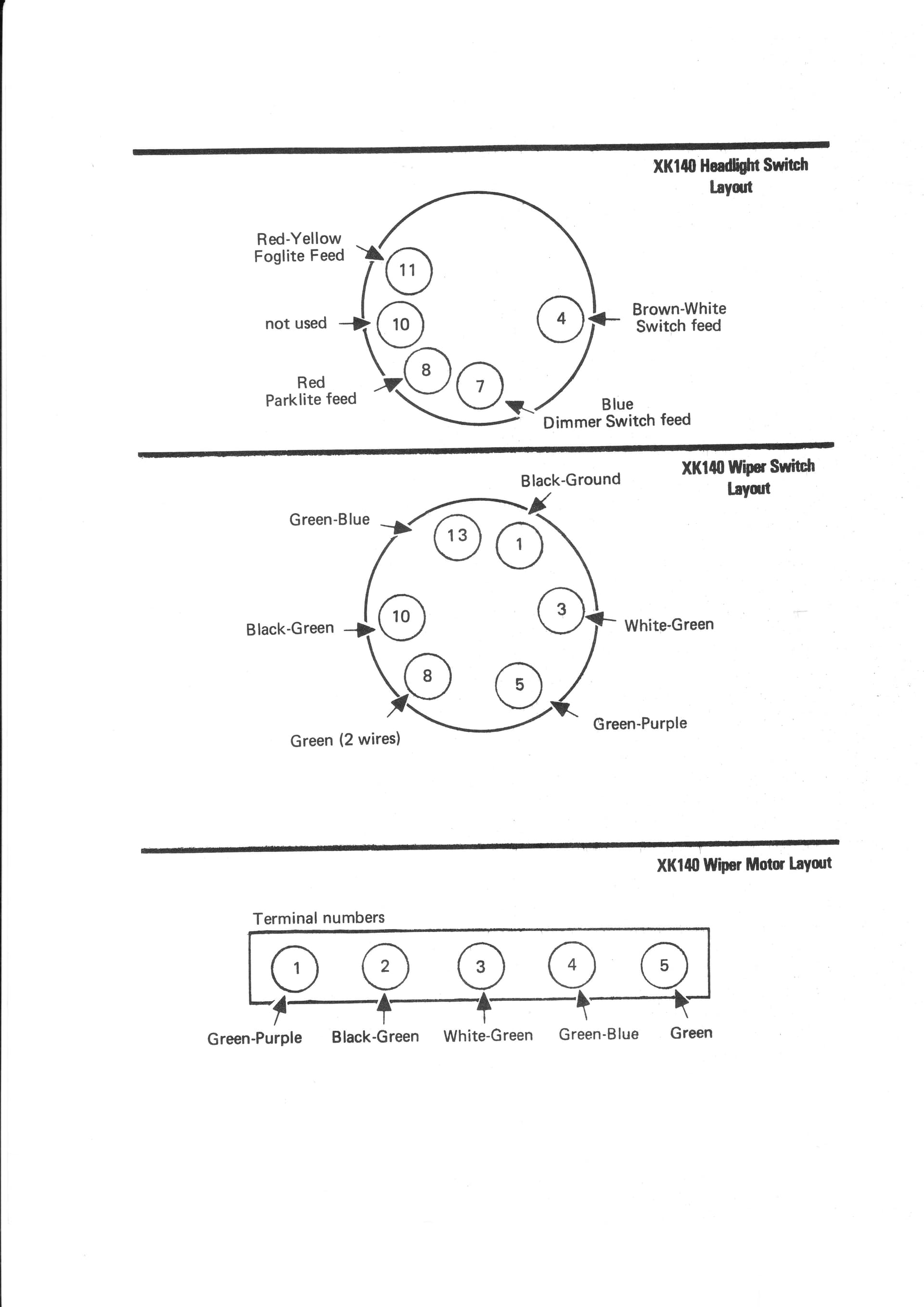
    There were two only versions of the LUCAS XK140 Wiring Diagram No.W26880 as issued in November 1954 but actually printed in December 1954, so very much to suit the release of the XK140 in October 1954, and the second version No.26880A as issued in March 1955 that is simply an update, but usefully on the rear of the single sheet diagram now provides the connection details for the Headlight Switch, the Windscreen Wiper Switch and the actual Windscreen Wiper Motor…
    See below a copy of the March 1955 Lucas Wiring Diagram…


I dare say these diagrams can be copied and expanded, as needed to read properly, if not send me a direct email - rogerpayne@bigblue.net.au - and I will send you a 2MB scanned copy…

Note however, this Wiring Diagram suits all XK140, OTS, DHC and FHC, RHD and LHD, including Fog Lamps (if fitted) and Interior Light (if fitted), but it does not include anything for the OVERDRIVE (if fitted) nor AUTOMATIC TRANSMISSION (if fitted). I am not aware of any LUCAS diagrams specifically for XK140 Overdrive nor Automatic, albeit they must have existed somewhere within Lucas and/or Jaguar, but seemingly never produced as a readily available Wiring Diagram or update of the March 1955 Diagram. However when I did all this WIRING work for XK140 EXPLORED I did draw up two separate Wiring Diagrams for both the early and the later Overdrive arrangement - see Plates 8-c8 and 8-c9 that again I can send copies direct, for those that do not have XK140 EXPLORED. I am loath to supply copied pages out of XK140 EXPLORED onto these public JagLovers web sites for my own-intellectual property reasons given the rampant unauthorized plagiarism by some individuals…
But no, I didn’t get around to doing similar for XK140 Automatic Transmission, as in the scheme of my then priorities and publication deadlines, I ran out of time…
In XK140 EXPLORED I spent a lot of work better illustrating all the separate circuits, components, connections and colour coding of wires being easier to read and understand than the correct, but basically presented LUCAS WIRING DIAGRAM - there are some NINE pages detailing all these separate circuits (including the two Overdrive circuits)

Next step was to turn this all into a physical practical reality regarding the looms, and practical routing of the looms, locations of all the components, and wiring connections to these components, but although a good start, this was not finished (HUGE amount of work, competing priorities, and a publication deadline, but certain work was done and included in XK140 EXPLORED, including the Plate 6-a2 shown in earlier posting - what did I say about ‘unauthorized plagiarism on a public web site’! :confounded:

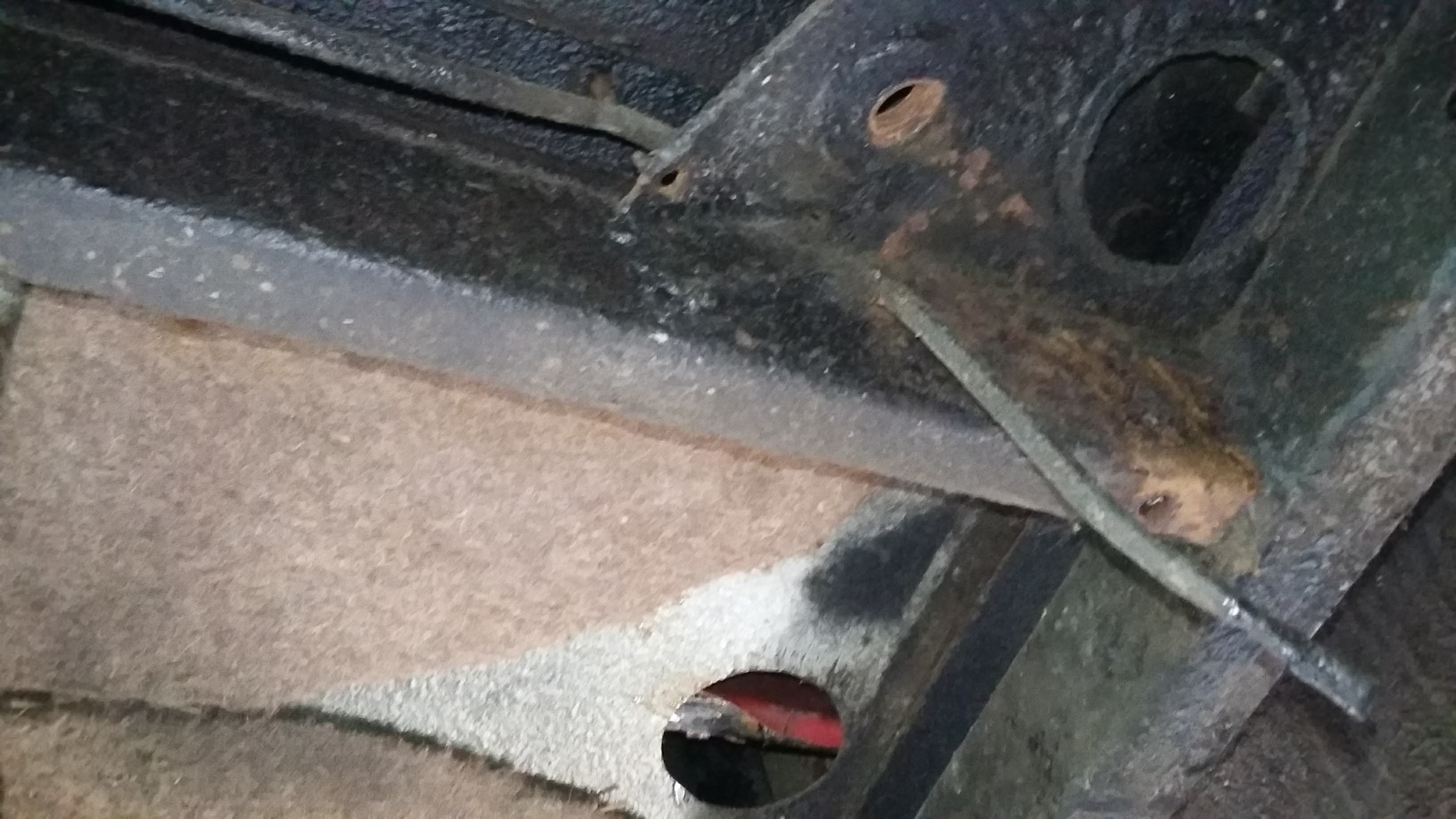
But the question about the ‘Loom inside Chassis Rail’… that is of course the Petrol Tank sender unit/Petrol Pump loom… If you look at the discussion on (as it turned out) XK120 Petrol Tank Senders in another thread, I did post three or four very detailed/accurate photos of this looms connections to the petrol tank sender unit, and its subsequent routing up and over the side and rear cross member and entrance into the right side chassis rail - but again I do have more photos I can send direct… But yes, this is a cow of a loom to correctly route on top of the rear crossmember and then inside the right side chassis rail, even when the body is off the chassis…

But another comment is all of this is easier or harder, depending on the source/manufacturer of your new reproduction wiring loom, not just correct wire colour codes, and correct layout/dimensions of all the various wiring looms, and all the correct connectors for each wire…, but also the rating and diameter of individual wires and the resultant diameter of the looms, as an oversize loom can be impossible to fit through small holes designed for original Lucas loom, and there are also some tight corners and restricted space to route correctly many of these looms…
I had a very close look at this some years ago now, so qualify my comments that some of the lesser quality/accuracy looms on the market may (hopefully) have improved, but back then found the BEST loom in all respects was made/supplied by Rhode Island Wiring (in USA - and as it happens, in Rhode Island :smiley: ), and indeed second best was made in Western Australia, and others then checked from both Australia and UK to be kind ranged from the ‘rest’ to ‘dont touch’
So I purchased my new loom from Rhode Island Wiring, that the observant may appreciate is in a LHD dominated market rather than my RHD XK140 loom requirement in Australia, so again some research, which revealed that the LHD XK140 loom(s) were 100% suitable/same as that for a RHD XK140 apart from THREE only wires outside their looms were too long, and for my RHD car simply had to be cut shorter to suitable length. If the Rhode Island LHD loom was not 100% suitable for my RHD XK140 I would have purchased second-best from Western Australia…

Others may have different experiences/recommendations than I…

Roger Payne
(co-author and intellectual property owner of XK140 EXPLORED)

Firstly, thanks for your detailed response Roger, and I apologize for reproducing plate 6-a2 in my post above. This has now been removed - as an author myself I should have known better. I put it down to a lack of concentration!

I understand entirely your views on wiring diagrams and loom products. These cars are not at all complex to wire functionally as the electrics are minimal and the standard Lucas colour coding is easy to understand. I do have the wiring diagram you posted above, but haven’t got to that stage yet as I’m still routing cables.
The irritations start with harness manufacture, as you say. With no wider experience of Jaguar restoration, I cannot justify trying different manufacturers to see which product is the closest, and if contacted each will, of course, proclaim theirs to be correct - or (for Autosparks, anyway) will ask what changes you want, an impossible question to answer on your first Jaguar restoration.
I have found Autosparks to be good, having used them for a very wide range of vehicles over the last 40 years. Not perfect though - the highlight being a '65 AC Cobra, for which only one wiring diagram was ever produced by the factory. This diagram omits many significant circuits and systems completely and seems to be a loose copy of the Ace’s, and of very limited usefulness. The problem there is further complicated by the very much more ‘hand-made’ approach of AC Cars (Thames Ditton) Ltd, with (almost) no two cars the same. Major components can be sited in completely different areas underbonnet in cars built within weeks of each other. As a result, much surgery is needed to make these harnesses fit but, as I said above, the nature of the colour-coded system makes functional connection pretty easy. I’m no stranger to open-loom surgery.
The difficulty with the XK, for me, is purely routing of the cables to get things close to the way Jaguar did it. The car was not a reliable pattern on dismantling as it must have been rewired in the US, with plastic wiring tape and no guarantee of correct routing. It also had a terrible conversion to an externally-regulated alternator which involved hacksawing out the N/S front wing stay, but that’s another story.
I’ll ask again if any other harness routing is not clear, but without pictures…
I’m looking forward to attempting to route the sender wire today, which should be great fun. But it’s Friday, which means cocktails at 6pm, always a great incentive.