Little by little i’m closing in on my Check Engine Light (code 4) problem.
According to my Alldata troubleshooting guide when warm with the engine running the O2 signal wire should send an oscillating voltage reading to the ECU between .9v and .1v. If it just stays at around .5v with no oscillation (which is what mine is doing) there is a short in the signal wire between the sensor and the ECU. I’ve already used a jumper wire to test the signal wire for continuity and it passed, but of course if it’s shorted with another wire I would still get good continuity.
So the next step is to cut the sensor wire coming out of the ECU and run a wire directly from it to the O2 sensor connector, totally bypassing the existing sensor wire in the wiring harness. Fingers crossed.
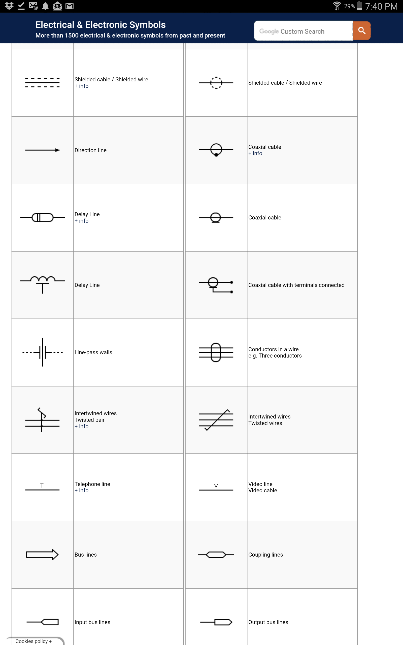
But I do have a question of reading the schematics on the signal wire. The sensor wire color is labeled as “INN” which according to the Haynes manual means “NCA” … groan … which means no color available ! Actually it’s a fat blue wire but what I’d like to know is what the dash lines next to it in the schematic means …**
It doesn’t show up in any of the color or symbol legends.
I’m not anything like as competent as you are with electrics Groove, but from a non-technical POV …
as both the CPS and the o2 sensors are the only units indicated with dashes AND because both signals are a “pulse” rather than continuous … perhaps that is why they are shown with dashes? I mean, what else could it be?
Groove, the dashed lines indicate a shielded wire, generally used if I am not mistaken for wires that carry an electrical signal to avoid external electrical interference with that signal:
Thank you guys for pointing me in the right direction …
“Shielded Cable: When To Use. … This is why data and signal cables are usually protected with insulated conductors and wrapped with a conductive layer. Shielding reduces electrical noise and reduces its impact on signals and also lowers electromagnetic radiation. Shielding prevents crosstalk between cables near each other …”
A shielded wire would explain the greater thickness. Now the problem is trying to pull the shielded wire out of the plastic connector at the ECU so I can insert the jumper wire. I need to order one of those wire connector extractor kits. Sadly I’ve never had much success pulling Jaguar wires out of their connectors
Can’t you backprobe that wire at the ECU whilst leaving everything connected? I haven’t been there and done that but I have read a bit about it…and I did stay at a Holiday Inn Express last night!
Gentleman, Gentleman, a little automotive decorum if you please …
So now I’ve learned that the signal wire from the O2 sensor is shielded and that shield has a ground wire attached to it. It makes sense then that somewhere along the wire bundle my signal wire has been damaged and come in contact with the shield, therefore also grounding it.
The problem in troubleshooting this is… I can unplug the signal wire at the sensor and run a jumper signal wire from the sensor to the ECU. But if I simply back probe the jumper wire into the ECU connector without removing the original signal wire (which I don’t think I can do without a special tool) won’t I still be getting an erroneous ground ?
Of course I could cut the original signal wire at the connector but If it turns out this isn’t the problem then … more headaches. I need to figure out how to remove the signal wire from the connector.
Most pins have a tab that snaps over a clip inside the connector - the idea is that it can’t be removed as it’s locked in there. In order to remove the pin, you have to locate the tab down inside and beside the pin. Once you’ve determined which side of the pin the tab lives on, you have to somehow insert a probe down there and push the tab back so it clears the clip. Not easy but it can be done …
Steven … Yes I see on the wiring schematics that the shield around the O2 signal wire is only grounded on one end. My question would be once it’s grounded why would you want to ground it any more? What difference would it make?
Larry … I’m looking for an extractor kit online with these types of probes …
Groove I second Larry’s thought about making up a tool. I don’t recall what he was improvising for but years ago my father made up a tool by grinding down the sides of a tweezer…