I�m ready to replace my aging TPS for the newer “red” TPS I got from John�s
Cars. All the parts are there (according to the pics in the Jag lovers pic
page), however, I did not receive any instructions from John�s Cars on HOW
to do it!
I�ve been looking through the archives, but did not manage to find an
installation process. Does anyone have some instructions in digital format I
can get through e-mail, or a step-by-step explanation on how to do it?
Although I’m sure SOMEONE will tell me I’m wrong I will tell you how I’ve
been doing them for years without the Lucas tool. First remove the throttle
rods from the throttle turntable, then remove the accelerator cable. No need
to mess with the nuts holding the housing on, just the cable end. Remove the
four 1/4 inch (7/16 socket) nuts holding the turntable to the pedestal. Flip
it upside down & unbolt the TPS (7/32 IIRC). Gently unplug the connector by
wiggling it & pulling at the same time. Mount the new TPS ensuring the
pigtail is going the right way. Leave the screws a little loose so you can
rotate it. Plug in the connector. You need a digital voltmeter to do the
adjustment. Ground the black lead of the meter & slide the point of the red
lead under the “boot” of the connector on the red wire of the TPS. Turn the
ignition key to the #2 position. Make small adjustments to the TPS until the
meter reads .360-.370 volts. No higher than .370 volts. Tighten the screws
for the TPS & recheck the voltage. If it is okay, Open turn the turntable &
let it snap shut 2 or 3 times. If necessary readjust & do the open/snap shut
steps again. If all is cool, reassemble. When you put the throttle rods back
on, you can adjust them as well. Put them on one at a time to adjust
properly. Remember that the knurled end of each rod goes to the turntable.
The other end of the rod (?) has left hand threads for the adjustment.
Loosen the nuts at each end and turn the rod slowly until either the
turntable or throttle plate begins to open. Back off slightly until it is
closed & you have some “slack” in the rod. Tighten down the nuts, recheck
for closed throttle & closed turntable, then remove one end of that rod &
repeat the process for the other one. This will set the TPS properly &
ensure that when the turntable starts to rotate the throttle plates will
start to open at the same time. If you have too much slack in the throttle
cable it can be taken up with the adjuster nuts at the turntable. Once
again, just make sure the turntable is still against its stop when you are
done.
I�m ready to replace my aging TPS for the newer “red” TPS I got from John�s
Cars. All the parts are there (according to the pics in the Jag lovers pic
page), however, I did not receive any instructions from John�s Cars on HOW
to do it!
I�ve been looking through the archives, but did not manage to find an
installation process. Does anyone have some instructions in digital format
I
can get through e-mail, or a step-by-step explanation on how to do it?
This is the closest archive I found to my question, but this still does not answer my question.
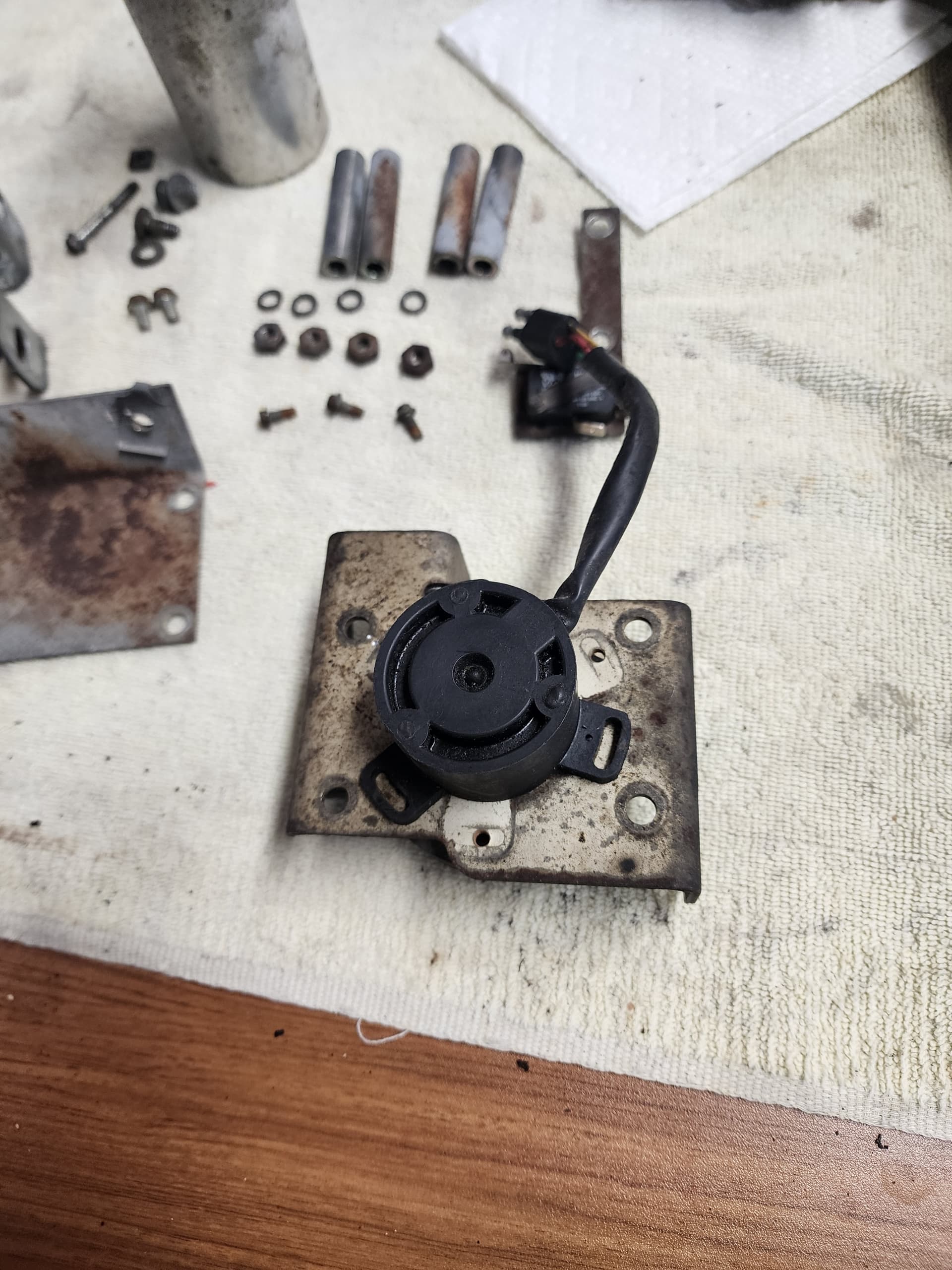
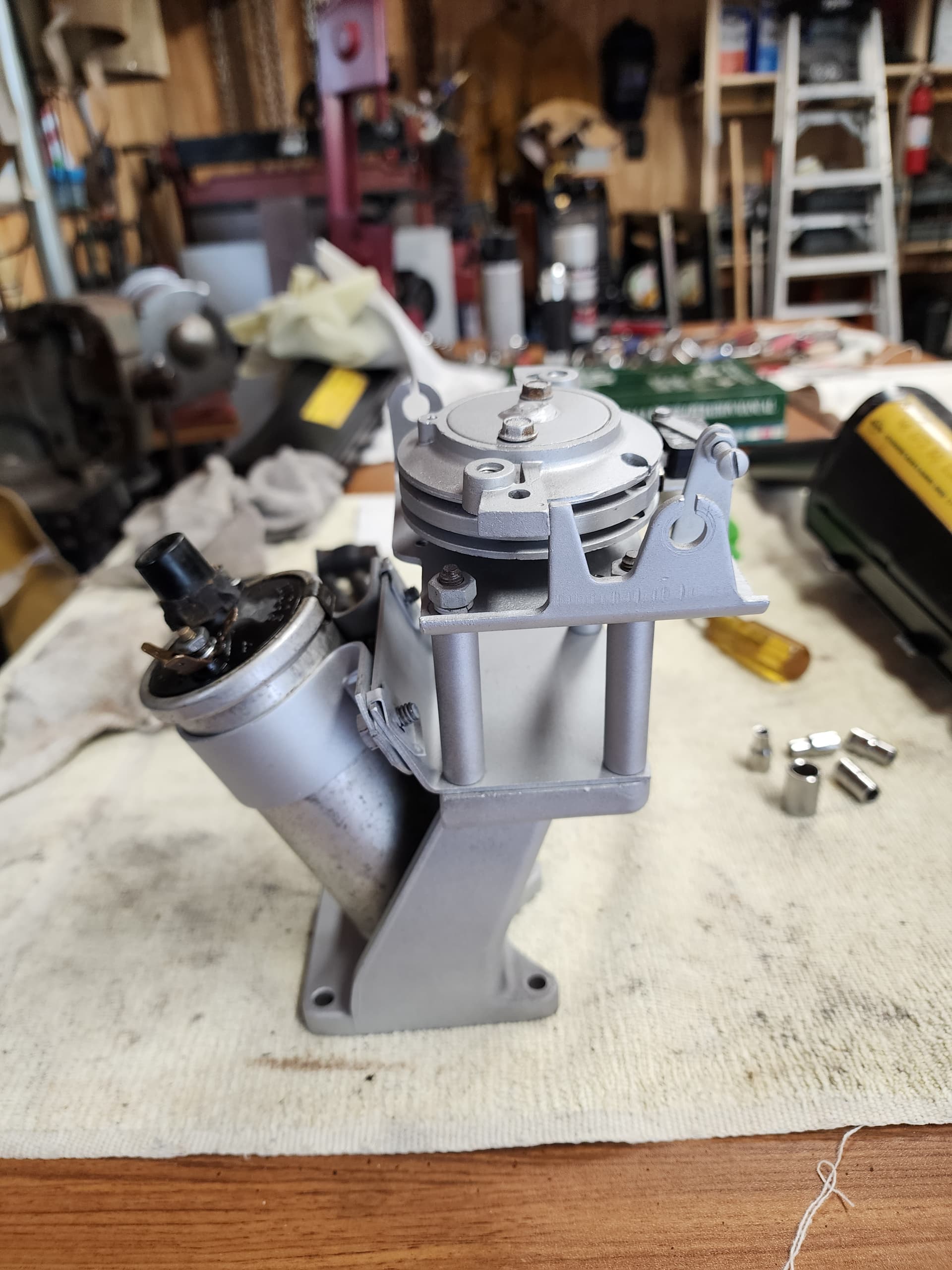
I am separating all of the throttle pedestal components to I can thoroughly clean, then paint, the metal components (some have surface rust on them).
The TPS is the old black type (likely original) and works perfectly, so I do not want to damage it while removing it.
I have the throttle pedestal completely disassembled … with the exception of the TPS, which does not want to come off.
I have the three bolts which hold it on and in place removed, the TPS twists (rotates) some on the bottom, but resists being pulled on to pull it off - so I have not applied very much force to pull it off not wanting to damage it.
I would also like to check the inside to see how it is holding up, or if this may be a good time to replace it.
After looking at the parts book drawing multiple times and seeing only and flat sided shaft going through to the TPS, and a flat sided matching hole in the TPS, and multiple easy prying attempts so as to not break anything - the TPS made the faintest budge …
Which confirmed that it was just push-on and stuck in place after 40 years.
A couple more pry attempts and it moved noticeably, then pried off easily.
Looks like I won’t be separating the TPS, but I will used my multimeter to watch for inconsistent ohm readings as I turn the pot shaft.
FYI, the new improved red one (used on Facelifts i think?) requires an adapter kit, which is NLA. I managed to find one used from an xjs that had already been converted.
I checked the operation of mine and it is not consistent when turned throughout its range. While it is not horribly bad, if is not smooth and consistent either.
I will be opening it to see if it is worth modifying it as described in the book (depends on what resistance strips look like inside).
My new question is that the book says “same resistance as the original at both ends of its travel (from .05 to 3.5K ohms)”, yet mine reads reads 4.7 to 5.0k ohms at spring stop idle position, and .25 to .30k ohms (250-300 ohms) at full WOT position (showing some of the inconsistent readings).
In the meantime, I ordered the Ford TPS part number, E7DF-9B989-AA, shown in the book.
Less expensive than the original or the red replacement by a factor of 10. Cheap enough that if the resistance range is not as stated in the book, it’s cheap enough to keep just to see if I can do anything with it (add a resistor in series if too low resistance, or maybe add another pot in parallel to play with it if the resistance is too high … it has been a lot of decades since I played/worked with individual parts in circuits calibrating and repairing oscilloscopes, voltmeters, signal generators, and all kinds of other stuff in a Standards Lab at a defense plant.
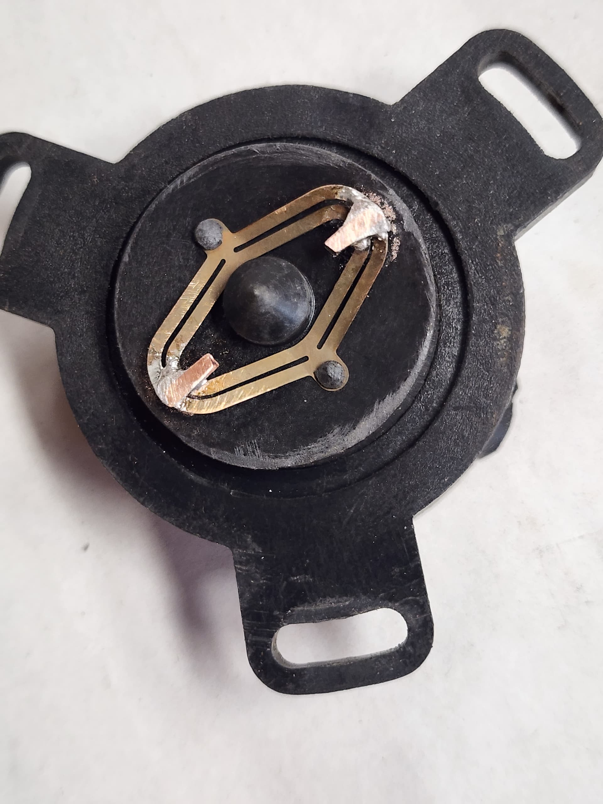
I’m one of those people who buys things, then alters/modifies/(sometimes even Frankensteins them) those things so I can use them for what I want/need. Thus the “I decided to cut off the 4 contacts, shorten them by about 1 mm and resolder them” rekindled my senses and thinking.
Since you’re cleaning it up so nice, switch to four stainless steel serrated nuts. I did. Look good, and don’t need lock washers that fall into Vee way too easily.
With my eyes the way they are (slight double vision), I won’t be trying to cut, reposition, and resolder the sliding contacts.
However … the sets of double contacts look like they are waiting for a jewler to solder a short gold contract wire between the each contact of each double set of contacts with the gold wire projecting inward an extra 0.070", for a total gold wire contact length of 0.150"; which would then provide contiuous contact across the unworn surface area. A possible solution?
(Replaced photo with correct annotations, had incorrect annotations before. )
I was thinking of a single wire attached to the side of the outer contact point, extending slightly outward to contact good surface, and extending inward past the inner contact, as you did, to contact more good surface.
I was thinking of using just a single wire out, but I like your out-and-back-loop.
I was also thinking of a wire the size of the existing contact point so its surface was just beyond the surface of the existing contact point; however, your photo looks like you removed the existing outer contact point?
Or is that just an optical illusion and that existing contact is just hidden in the solder?
I checked with several jewelers here and none of them had gold wire. Seems that they all use laser soldering/welding equipment now and the wire comes on a spool (like for my MIG welder), but unlike my welder (which I can feed wire out) they said their couldn’t do that (which I find a bit doubtful).
And because they use the lasers, they could solder/weld to the copper/brass spring contact arms (would melt the copper/brass).
My solution: cut off a short piece of 14 AWG solid wire in my workshop, and solder that next to the existing contact points, then file the #14 down as it was about 2.5 times thicker than the contact was high.
Took a bit with my vision issues, but finally got the two pieces soldered on.
If someone is going to do this, as stated by others, the screws are not very deep. To save as much screw head as possible, stop drill it out at first sign of metal drillings coming up.
My ohm meter shows 4.5 k ohms green to yellow, and fairly consistent changes red to green/red to yellow after completion, indicating that, while it isn’t “like new”, it isn’t too bad either.
After everything goes back together, I’ll know how it works. Will have the Ford TPS as backup if needed.
Gold wire or gold solder, would be an overkill.
I used silver, just because I had some lying around as I am a jeweler my self, but copper as you did, or brass, would do the job fine.
I used plain old good led solder.
Two things:
I don’t remember how much space is available inside the pot, but I think that your wire is too thick and it might press too hard on the track.
Tha tab must be absolutely flat against the carbon track, so it has the widest contact area and slides with the least force.
In order to shape the wire I’ve mounted the pot shaft on a electric drill and spinned the contacts against a washer with 400 to 1200 grit sandpaper stuck on it. The hole of the washer must be just big enough for the centering shaft to go through.
I also gave it a very good polish after that, you want it to be as smooth as possible so it doesn’t scratch the track.
Aristides, you are correct that the original diameter of the wire was quite large. I measured the height of the contact and the contact arm, which was .035, and filed the wire contact I solderd on down to close to that.
I made sure the contacts were flat when pressed down by laying a piece of crocus cloth over the two resistance strips and rotated the contacts back and forth over that until they showed the same pattern across their length.
Then I assembled the pot and for testing to verify that it would work - it did.
Today, I’ll finish it by verifying contact thickness, then using some much finer sand I have to smooth out the sutface. I’ve got sandpaper up to 2000 grit, maybe even finer.
I agree that the contacts shouldn’t have any unneeded pressure on the resistance strips. Matching the thickness of the original contacts and using the original contact arms should accomplish that as best possible.
I was trying to find gold wire as gold contacts make the best contact, when I couldn’t, going with copper works quite well for electrical work, and small using rosin core electronic/electrical use solder too. Do not use acid core solder for this work.