XJ12 5speed conversion

Agreed. As long as the nose of the input shaft is not galled up or damaged, you are fine. The only reason to give it to the machinist is so that he can cut the ID of the pilot bushing to a matching slip fit. He should not be cutting on the input shaft.

Agreed, mine measured .750". Which makes sense, a nice round number, 3/4 inch.

The bolts to hold the pressure plate to the flywheel are special (pretty much always, not just on Jaguars.) If you look at the holes in the flywheel, you’ll see they have no threads for the first 1/8" or so, they are counterbored to the same size as the holes in the pressure plate.
The proper bolts have a shoulder on them which goes thru the pressure plate and into this counter bore and locates the pressure plate. If you look on Summit Racing or any similar site, and search “pressure plate bolts,” you’ll get lots of options.
You need to find bolts that are the right length. If they bottom out in the flywheel (either because they are too long, or because the shoulder on the bolt is too long and hits bottom in the counterbore) then your pressure plate won’t be properly seated against the flywheel.
It’s not hard to solve, just something to be aware of. I bought a couple of sets from Summit and picked the ones that fit best.

I missed it altogether. I gathered he was suggesting give the machinist the input shaft so he can machine the bushing to fit it.

1 Like

Yep. Except even with the bread trick I suck at sweating copper pipe. I now use the beer trick. I open a beer and call a real plumber.

1 Like

Got it. The pressure plate should be tight before the bolts bottom out. I suppose if it were borderline, a hard washer -shoulder diameter -could be placed under the bolt head while still engaging the counterbore and having enough thread engagement. Parts are on order. Not sure if the pressure plate comes with shoulder bolts, but I know the kind you’re talking about.

Thanks,
Tony H

Correct. Some bolt sets come with washers. Also, and I think this is in my thread, I could not find an obvious spec for torquing the pressure plate into an aluminum fly wheel. I think I settled on 18 foot pounds. But don’t quote me, I’m sure I called it out in the thread.

Also, let’s touch base before you start indicating the bellhousing. That is super critical, I’ve learned a few things, I just haven’t had time to update the thread. Let me know when you get to that point and I’ll make sure I get the information to you.

Bob Brackney

Time for an update. New pilot bushing is installed. After a detour through two alternative paths, I ended up just where we left off: Having a machinist open up a 3/8" ID oilite bushing to .492" and ream it to .494" after installing it. The alternate plans were to either have the shaft lightly precision ground a few thou,- not breaking through the hard layer -just to clean it up, OR do the same with the addition of spray welding it oversize and grinding it down to stock size to use with the stock bushing. I liked this last idea best. Trouble is, I couldn’t find a capable machine shop that wasn’t understaffed and buried in work!
I ordered the same pressure plate kit as Bob B. used: RAM 88760. Tried to buy just the pressure plate but it cost the same as the kit, so I got the kit. Had to get a different disc though, because the PP is for a Chevy while my input shaft is Ford 1-1/16" instead of 1-1/8". (Both are 10-spline). I bought a bolt kit as we discussed and found they were just a thread too long, bottoming out in the flywheel hole. I found 1/8" spacers in my local hardware store that will work fine.
Got the pedal box out. It was fairly easy. ROM describes the process well and the 6 fasteners are easy to get to. Hint: use your smart phone camera in selfie mode and a 1/4" drive ratchet with 6" extension. With the phone laying flat on the floor, you can easily see where the bolt heads are without twisting and torquing your back to get your head under the dash! I am now modifying it per instructions in the kit I got from Vintage Jag Works. Need to trim down my brake pedal and have someone weld a scrap piece to the top edge. The “reformed” brake pedal will be narrower and taller.

All of the above has not taken too much time to do and I’m still waiting on my bellhousing. In my spare time I am cleaning up my leather upholstery and considering a redye in a different color. I’ll save that for a different posting.

Tony H.

1 Like

Slow going but some progress to share.

I am having to do more fitting and adjusting than I expected. A space heater, scrap lumber and sandpaper have become unexpected but useful tools.

When I first tried to install the aluminum flywheel, it wouldn’t quite fit. There is a recess pocket machined in the mounting side that’s supposed to fit to the crankshaft boss but it wouldn’t go on. The Fidanza instructions note that there may be a “slight” interference fit and advise heating the flywheel on a hot plate to help with installing. I did not think a hot plate was a great idea (don’t have one anyway) so I warmed it with a space heater instead. Still, I had to press it on by slowly tightening the bolts in sequence. But after it seemed to be seated, the dowels wouldn’t line up. I torqued the bolts almost to their final tightness and checked the runout: About .005" at the outermost diameter of the friction face. (Red marks in second picture. First picture shows setup before I cleaned the green coating off.)

Flywh Runout Setup1

Flywhl Mounted3

The ROM understandably has no runout spec for this, or the flex plate. I did find several unofficial sources claiming that .0005" per inch diameter was a basic rule. So, if that’s true, I was near the limit with a new flywheel. I was not happy about this, especially when I realized I had painted myself into a corner because the flywheel was going to be very difficult to remove! But there was no way I was going to leave it on and proceed.

I considered making a puller out of the flex plate. But before I went to the trouble of doing that, I thought I’d first try to get the flywheel as hot as possible with the space heater and hammer it from the back side to see if it would move at all. So, I heated it for an hour to about 130F, turning the engine occasionally like a rotisserie. I found a 2x4 to hold against the bottom back side of the flywheel and whack with a heavy hammer. Then I discovered that the 2x4 fit perfectly between the flywheel and oil pan. I stuck it up there, gave it a good pry and saw it move a little(!) I turned the crank and gave another pry. Now it was cockeyed -good! I turned the crank again until I had the low side lined up and gave it a good pull. It popped off onto the stack of foam pads I had placed on the floor. I looked at the end of the crank hub and a piece of aluminum wire was hanging off of it. Ehh?
Flywh Removal

The crank hub had actually peeled a wire off the ID of the pocket as I tightened the flywheel on!

So, to get it to fit, I had to open up the recess ID. I thought about taking it to a machine shop but as was mentioned previously, it doesn’t really matter how well the pocket fits on the crankshaft, as long as its fully seated with the dowels in place. After all, that’s the factory setup; the flex plate has no pocket, it’s flat. The pocket just over constrains the fit. I measured the crank diameter and the pocket diameter and I came up needing to remove .005" from the pocket ID. So, I decided to sand it using a piece of stainless shaft I found in my junk box. I taped a strip of 180 wet or dry sandpaper around one end (after checking squareness ) and sanded in a circular motion, rotating the flywheel every so many turns. I used water to help prevent loading up the sand paper but also to lube the flywheel mounting face. (love that wet or dry sandpaper!)

Flywh Resize

Flywh Refit runot

After several test fits and more sanding with finer grit, I got it to go on with a bit of effort but once on, It was free to rotate to line up the dowels and torque the bolts without any drama. The runout now checked out between .001" and .002" but The measurements were not very repeatable. My setup seemed solid, and then I realized some of the bad precision could be thrust clearance in the crankshaft. So, if I’m down in the noise from crank thrust, I think that’s as good as it gets.

There is more to tell with the bellhousing and future adventures with other stuff but that’s enough for now.

Regards to all,

Tony H.

Good times – congrats on the progress!
Comments from the peanut gallery:
I would be interested in the run out at the very edge of the fly wheel, where the pressure plate bolts up. Friction surface is removable, who knows how flat it really is, and if there’s a bit of run out there it doesn’t really matter. I think what you care about is how flat the surface the pressure plate bolts to is.
More important, IMHO, is the axial run out, taken at the edge of the flywheel. Need to be sure that flywheel is exactly centered and running true around the crank, otherwise your pressure plate will be off-center, and you’ll have no end of misery, especially if you’re using a hydraulic throw out bearing. Yes, it should be fine if you got the dowel pins lined up, but given that you had to modify things a bit, I’d still check it to confirm.
Regards
Bob

Good advice. I repeated the face runout (what I call axial runout -or wobble) on the aluminum surface outside the friction surface. It holds at .001", so I’m satisfied with that. BTW, while I had the indicator set up, I checked the crank end play: .006". So, it’s not floating around too much as I turn it.

Different story with the radial runout measured on the edge.
RadRunout1

Got just over .005". So, I have a bit more to do. It’s possible that the first install, when the crank hub scraped material from the ID, created an off center oval that I just enlarged with my sanding. The first thing I’ll do is try rotating the flywheel 180 degrees and see how it measures then.

In any case, I’m glad you pointed out the potential trouble with the t/o bearing. If the pressure plate is not dead center, it’ll wiggle that bearing to death!

Tony

Good plan. This is something I never checked on my car but I assume it should be less than .005.
Maybe lever it side to side a bit before you unbolt so you know if there is any play there. Should measure less than whatever the bearing clearances are I would think…

Yeah never mind how I know that! :grimacing:

Last week, I assembled the clutch with disc onto the flywheel and put on the bellhousing to get some measurements from the trans mounting face to several key points:

distance to clutch release fingers, distance to disc hub, distance to pilot bushing.

Without getting too much into numbers, I found the distance to the release fingers is slightly more than needed for the hydraulic t/o bearing to engage. Good news; I will install some of the shims that came with the kit (RAM 78130) to bring the bearing closer to the release fingers. This will affect the “free play” or pedal travel before resistance is felt.

The distance to the disc hub is shorter than the length of the tube on the input shaft bearing retainer included in the kit. Bad news but easy to fix. (If you are getting deja vu reading this, it may be because Bob B. had the same issue with his setup -not too surprising since we used the same bearing kit and clutch.) I wanted to hear what RAM tech had to say about this and their reply was, just machine enough off the end to leave .100" clearance. Since I don’t have access to a lathe, I’ll machine it with a hack saw (carefully!)

DiscHubDepth

The pilot bushing gave me a scare. My first measurement was derived from the previous ones and it looked like the tip would just touch the outer edge of the bushing. Ehhhh? I went over my calculations and found the error but I also just stuck a tape measure in and saw that I’ll have about 15mm engagement. I wondered if this was enough since there is length and depth of the parts to give almost twice that. Surprisingly, there is not much information on-line about this basic quantity. One website quoted an unsourced rule of thumb that 3/8" was needed and the rest was “icing on the cake”. OK! Sounds like I’m safe, but talk of icing in this context doesn’t give me a lot of confidence… Dellow, my bellhousing source just said the spigot shaft should be 12mm longer than the mounting face. Good there, since they asked for the input shaft length in my order. I would be interested if anyone else knows conventional figure for this dimension? My gut sense is that it should be equal or greater than the shaft diameter; in this case 1/2".

PilotBushDepth

I have taken note of all this and will now move on to determining the shifter location and a finished dimension for the driveshaft.

Cheers!

Tony H.

1 Like

Good progress Tony!
Definitely shim the bearing per RAM instructions. It cannot be too much or too little. Must be within the spec. .150 if memory serves.
I used the hacksaw on my retainer. Ground and filed after. No problem.
15mm of pilot engagement is fine. I have a 428 ford/Doug Nash setup that has run at about .5” for 49 years. No issue. If it really bothers you you can investigate machining a custom pilot bearing with a shoulder that protrudes from the crank. But, that could hit on the clutch disc. If you’ve really got 15 mm, I wouldn’t worry about it.
Are you using the RAM HD bearing? Same part number, just has HD on the end. If not I would recommend that. It’s just a better design IMO.

1 Like

I cut about .30" off the tube yesterday and cleaned up the end real pretty…


…then I pushed the bearing sleeve down over it. Although I rounded the edges of the tube with sandpaper, it wasn’t enough to prevent shaving a piece off the internal o-ring. OUCH!
I wrote to RAM about getting a replacement but they said if the o-ring was still intact it was OK because it’s just there to prevent rattling of the sleeve on the tube.

I also asked them about the HD bearing. They said that the 78130 part IS the HD version. I suspected this. They probably just decided to replace the “standard” version with the HD version and drop the suffix. I do notice one thing in your pictures though. There’s one in post 138 after you shortened the tube that shows the bearing all the way down near the retainer base. Mine hits a stop about a half-inch above the base. No concern, just something different. -or is it just the picture angle?

Having seen/heard “don’t worry about it” regarding the pilot shaft engagement several times now, I’m going to take that advice!

I’m getting ready to try an alternative to installing the trans to the bell. I want the bell confirmed true and centered on the engine, not as part of the trans assy. A variation of your Option2 in 137.
Stay tuned!

2 Likes

Hi Tony-
Regarding the bearing hitting the bottom of the retainer base. Some bearing retainers have a shelf or a shoulder at the bottom, and some don’t. The one that came with my Ram bearing did not, the one that came with my transmission did. Either way, this is another one of those “don’t worry about it“ things. It just means you use a few less shims to properly space the bearing.

Just to be perfectly clear, the original ram bearing that I used was specifically for a T5, that is what I thought I needed. It included a special bearing retainer. Without a shoulder. I ended up with a different Ram bearing, but I still used the bearing retainer that came with the original “for a T5” bearing.

Also note that some retainers are steel, and some are aluminum. You want steel.

Given a choice, I always bolt the bell housing to the engine and confirm it centered, torque it to final spec and reconfirm it stayed centered. Then I install the trans. That is what I did on the Jag.

If for whatever reason you are putting the bellhousing and transmission in a car as a unit, there is no way to confirm the bell is centered. You can only hope that whatever measurements you took and adjustments you made before you joined the bell to the trans (e.g. offset dowel pins) held. The tolerances are so small that I have a low confidence in that happening.

Anyway, you continue to make good progress!

Bob how’s your 5-speed doing anyway? I might be tackling mine this winter.

Five speed is good, thanks! Up until the last couple of weeks it’s been brutally hot, so I haven’t been driving it much. However when I do, it works great and it’s a whole lot of fun.

I’m now scheming on a Sanden ac compressor upgrade as my r12 system that was charged in 2007 is finally starting to give up the ghost. But that’s another thread.

1 Like

I thought I had found a silver bullet in my goal to install the trans AFTER the bell was already in place. To clarify, I know from experience that in general, putting a trans onto the engine with the bell attached is a PITA because for one, the assembly is heavier and wieldier, and alignment is more difficult because clearances are tighter due to the width of the bell in the forward pocket near the engine. Alternately, when putting the trans on an already installed bellhousing, you’re working in a more accessible place under the car. It’s just easier to have a two-step process where you put the bell on, check its positioning and then mount the trans.

However.

The choice of using an internal hydraulic release bearing complicates things because that assembly, mounted on the front of the trans, can be too large to fit through the registration hole in the bellhousing. Bob B., using the two-step method, sidestepped this problem by pre-assembling the bearing in the bell, suspending it by its hydraulic hoses and threading the trans input shaft through the bearing support sleeve. See his post 137. This really gives me the heebee-jeebees! -especially since my bellhousing has no inspection hole to verify success.

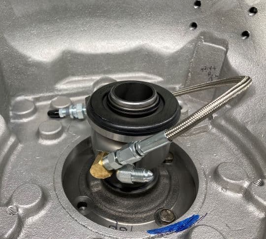
But, trying to salvage the two-step method in my case, I realized there’s a subtle difference between Bob’s bellhousing and mine: The registration hole in my bell is sized for Ford T-5 which means it’s larger (4.9" vs GM 4.67") which, I thought, would give me enough clearance to fit the trans through the hole WITH the bearing installed on the trans. I could tie a cord to the hydraulic lines and snake them through the bell and out the side access holes. But I found two obstacles to this in the way the hydraulic lines connect to the bearing: First, there are adapter fittings that come straight out radially and exceed the hole boundary. To correct this, I thought I could use angled fittings (the aforementioned silver bullet). But second, as the pictures show, the hydraulic ports are too close together to install both of these fittings. The first one goes in OK but it stands in the way of putting on the second. I found a street elbow fitting which is small enough to screw in next to the angled fitting but the assembly is still a tight fit and would require cutting the bellhousing for extra clearance (blue mark in the picture). I don’t like this idea.

HydConnections3

I found another non-advantage for me in following this track: In “rehearsing” checking the bellhousing runout with the clutch installed, I tried to mount my dial indicator on washers clamped to the diaphragm spring the way Bob did (his post 219) but I could not get consistent readings because the magnetic base would not stay put. I futzed with this for hours wondering if the bellhousing was really that far off. ( I had checked it when new and had to install .021 offset dowels to bring it within .005" TIR)

So, I stripped all the parts off and mounted a plate I had previously made to the crankshaft. It’s tapped to accept the indicator post without the base; won’t slip! I re-installed the bell and rechecked the runout. I got .002", which gave me confidence that the bell positioning is robust and repeatable. One reason may be that the dowels are very tight in the bores and don’t move unless you were to drive them out
Bell runouts Red/ Black -lateral/radial runout

All of the above means, as unsavory as it seems, I’m leaning toward installing the bell and trans assembled. That way, I can route the bearing and hydraulic lines in a neat and orderly way on the bench and avoid hacking up my bellhousing.

However, I realize as I write this(cartoon lightbulb over my head) that I could try the Phoenix two-step, not worry about the bell measurement, and see if I can successfully skewer the bearing tube. I’ll call it Option 3. If it doesn’t work out, I can regroup. -cross that bridge when I come to it.

2 Likes

I bet you can skewer it. All you have to do is get it started over the nose of the input shift, there should be enough room to do that with your hand. Then as you slowly move the trans forward, the bearing will center itself and slide over the input shaft. It will take a little bit of a bump to go from the splines over the bearing retainer, but I bet it will work, especially with a little bit of grease. You could also cut an inspection hole…?
PS don’t forget to tape the fittings :expressionless:
Bob

Yea, I hate the idea of cutting a hole but if done near the bottom below the two lowest mounting bolts, it shouldn’t affect the bellhousing’s strength. No stresses down there because it’s not supporting anything. I could get my hand in a 3" hole and guide the bearing in, though the flywheel and clutch will be impinging in that space.
I’ll keep my teflon tape close by!

Tony

I didn’t use the access hole for anything except to peek through and confirm that things were progressing as I thought My throwout bearing just kind of sat there supported by the steel braided lines with the fingers on the clutch kind of pressing against it. It was really very easy.

Bob Brackney