
Hi, can someone advise me on the correct wiring here?
Is it the ignition relay or horn relay hanging there?
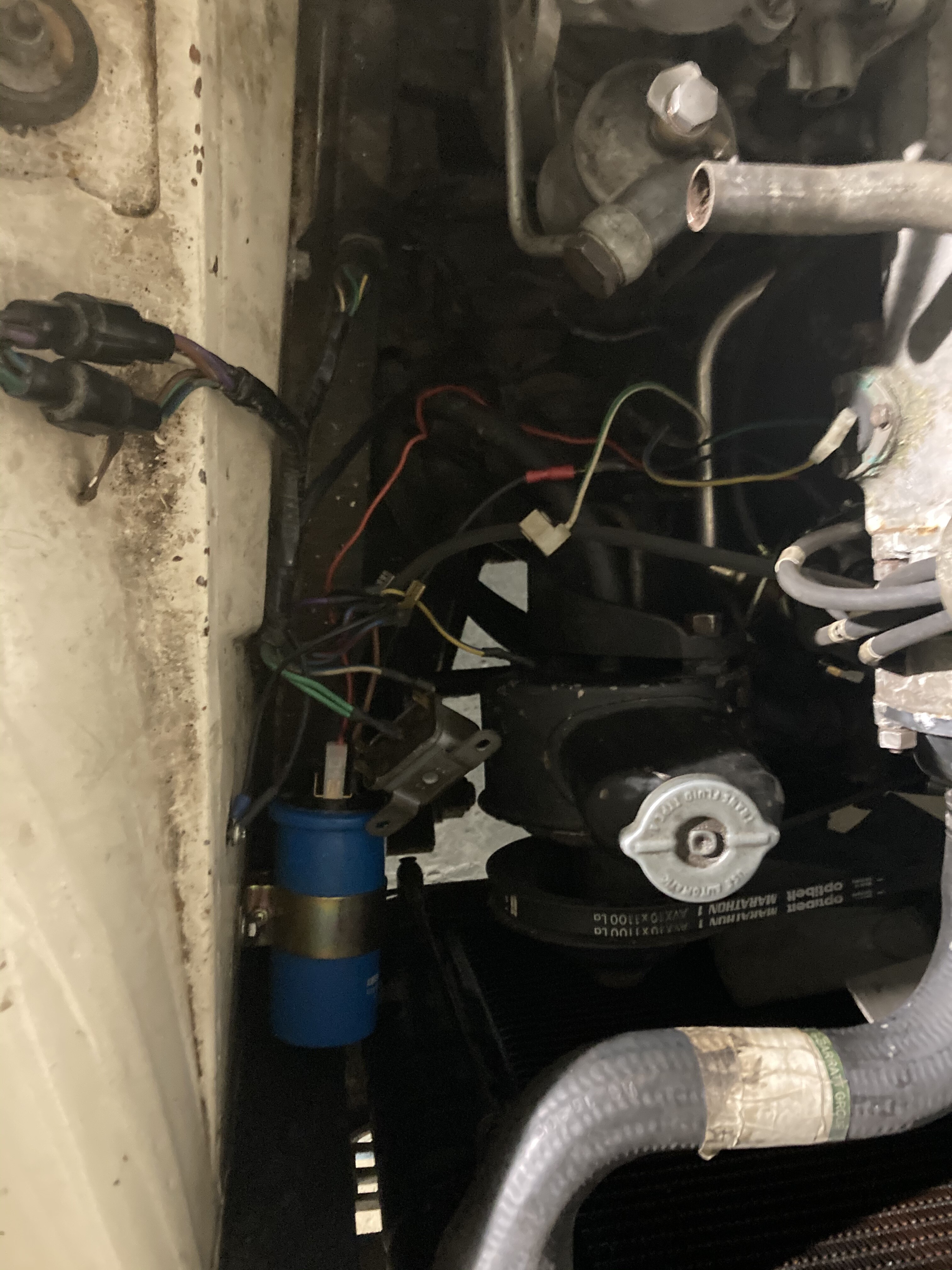
Front right side of engine.
Cannot seem to find colour coding to match the Haynes manual.
Had someone to look at it some time ago when it was all connected and the engine started. He disconnected everything and now I’m a bit lost…
1 Like
Welcome Christian,
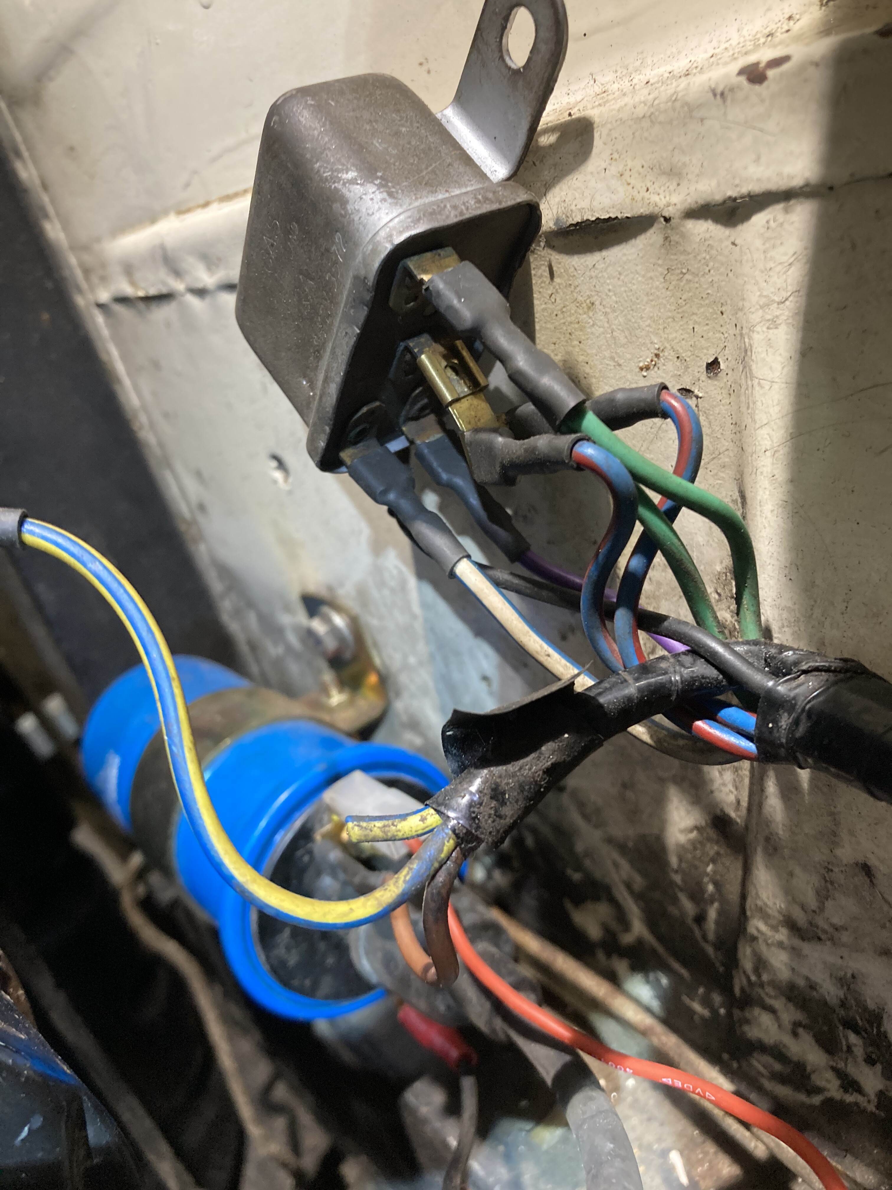
it looks like you were shooting down the right fender well. On my SII 4.2 litre car the coil is mounted to the engine, but indeed the horn relay is located around the same location. And yes, one post in is green, the other in is brown/green purple/brown, the ones going out are purple/black (to the horn push and ground) and purple/yellow (to the horns).
I’m not sure though whether the relay is mounted to captured nuts or through the fender wall.
Show us more pics! Where are you located?
Jochen
75 XJ6L 4.2 auto (UK spec)
I think purple-yellow/black is commonly used for the horns. Green is powered fused from the ignition per some of the British wiring standards. Find yourself a chart online, a lot will match up  Both points to this as the horn relay, but I can look Tuesday on my (4.2 is of course different in some regards, but) 1969 LHD. Is yours white or by chance ascot fawn?
Does the horn not work?


Easy way is check the horn just below for its wire colour also trace the wires from the (remote, right?) starter solenoid.
David
**
Wire colors is the only way to decode wiring diagrams, Christian - and if wires are not positioned correctly, everyone is lost…![]()
It sure looks like the horn relay, and is in the right place - but even if misconnected it should not interfere with engine running. Any loose wires in the area…? And was that the only area ‘someone’ fiddled with? And does the horn work…?
Frank
xj6 85 Sov Europe (UK/NZ)
**
Thanks for the response.
Your inputs directs me to believe its the horn relay and thats a good starting point.
The horns are, as of now, mounted below engine, but not connected. The wires are hanging lose.
As this is a series 1 it differs too much to compare with a series 2 I’m afraid.
It looks like original wiring, no reason for it not to be, but I haven’t found a wiring scheme online clear enough to guide me.
I’ll try to get some better pictures today.
The wires that run alongside the hydraulic lines in the same brackets are the ones for the horns. They ground through the mounts.
Christian,
the main difference between SI and SII - from an engineering perspective - is the different carbs (early SI use SU HD while late SII use SU HIF and those in the middle share SU HS) and the heating/ventilation.
I seriously doubt that the wiring pattern will wildly differ between both cars. In fact, the SI wiring scheme I just checked out shows the same connectors as the SII wiring scheme: Green wire from fuse #1 is mounted at post w1, purple/brown wire from fuse #4 is mounted at post c1, purple/black wire goes out at post w2 to the horn push and ground, while purple yellow wires go out at post c2 to the horns and ground.
The 2.8 litre version was the attempt of Jaguar to skim the cream off the fleet buyer market. Entry level cars came with 4 speed boxes without OD, no leather, no power windows, no a/c and not even a central armrest. Very early European cars had a “2.8 litre de luxe” version including leather, power windows and central armrest. I’m not sure whether the austerity version survived in Europe.
Good luck
Jochen
75 XJ6L 4.2 auto (UK spec)
Thank you Jochen! I will indeed double check tomorrow, and compare your wiring with what I came to today.

The Yellow Blue is the only one in the wild at the moment, I think…
Mine is a Series 1 1969, European LHD, white, leather seats, chrome instrument bezels, no air con or electric windows.
I really appreciate all your kind advice!
The one I almost bought had no central armrest etc., but OD!
Speaking of which, yellow/blue could be OD by the standard but what would it do in that location - maybe something else. You have to go through quite a mess, let me know if you want some pictures. Mine‘s original from what I know.
Correction: blue-yellow: electric speedo. To the coil. Don’t ask me which post but I can have a look.
Christian,
whoever was there before left a bit of a mess behind: your first pic clearly shows a blue/red and blue/white wire at the relay - these belong to the “dipper switch”! In a similar vein blue/yellow should go from the head light switch to the fog light switch (please note that the wiring scheme says blue/yellow, while your wire looks like yellow with a blue tracer …; do you have fog lamps?). The wires to the coil look youngish.
Sorry, I forgot to mention: SI cars don’t have the dipper function for high and low beam at the steering column stalk, but have a foot switch and my diagram doesn’t show any separate relay. Maybe a relay similar to that of a SII car was fitted to your car (in SII cars they are located at the left end of the upper crossmember over the radiator)?
The original horn relay is a Lucas 6RA - you might be able to read what appears as a print on the frontside of the relay in your pic. It is supposed to sit vertically at the height of the p/s pump - maybe where the coil is mounted now? That being said I just found an indication that SI cars had their coils mounted at the right hand fender well and another Lucas 6RA relay mounted at the bulkhead.
Seriously, if I were you I’d try to get my eyes and camera on an original SI car and check out where the parts and wiring looms are located and connected …
Good luck
Jochen
75 XJ6L 4.2 auto (UK spec)
You’re right, something is wrong here.
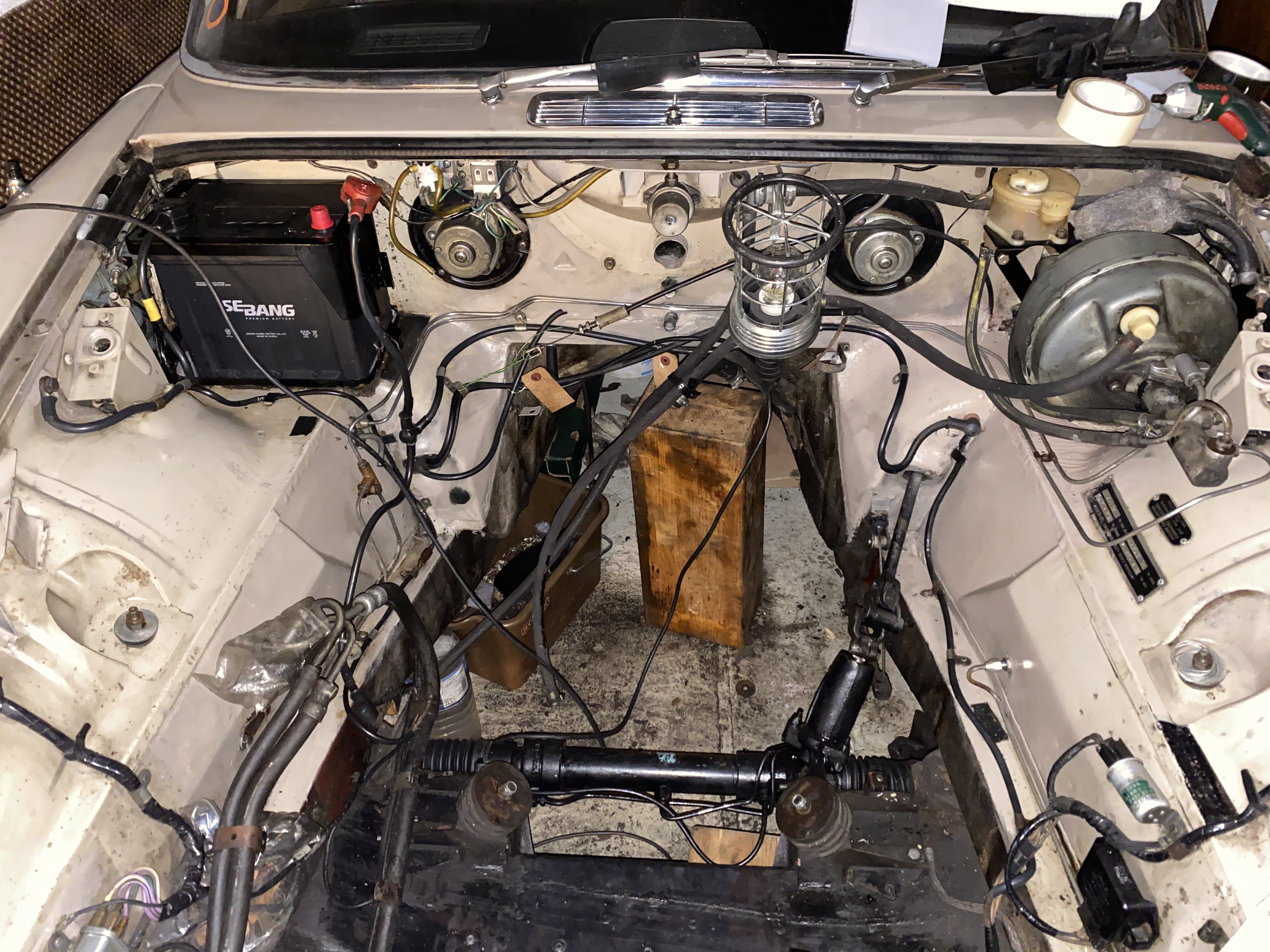
Is the round thing at the top original? Are your wires routed like mine?
And I‘ll check my manuals for a better guide

Thanks guys, let me first say that headlights and foot operated high beam works without the relay in question connected…and there is a dip function on the left stalk on the steering wheel.
Jochen, to use a S1 as reference was my intention, and the reason I so rudely rejected the S2 suggestion. My apologies.
The ‘young’ wires to the coil are from the new electronic ignition module. Thin red +, black -
David: thanks for the pics, helpful as I see the circular connector is not present on yours, on mine it changes some of the colors and so contributes to the mess. Slowly getting there. To be continued.
Since you seem to know your S1’s- where should I start looking for the chassis number on the right side wing? The actual stamped- into -the- body number. Not the plate on the left. Cannot find it. And searching forums haven’t supplied me with an answer.
Again, thank you, thank you!
1 Like
No sweat, Christian,
looks like you’re getting somewhere: you’re right - there is a switch at the column stalk, but that’s only the flasher switch. Permanent high and low beam is operated via the foot switch. For clarification could you check the wire combo at the foot switch? There should be a blue/white and a blue/red wire going out for high and low beam. And to cross-check: if you pull the blue/red and blue/white wires from the relay in your picture, does it affect function of your dipper switch?
Getting back to the horn relay: it should be mounted like on David’s pic. The same pic shows the wires should come down from the main loom running along the upper trailing edge of the fender well. In your second pic I see two large connectors that look strange to me. You might try to shed some light on them. As for the wiring of the horn relay, the colors I described should be correct. Maybe you find them behind these connectors.
Body no. is stamped in underneath the rear bumper (right side)
; car no. on right front fenderwell where the diagonal strut attaches (both on SII cars).
Good luck
Jochen
75 XJ6L 4.2 auto (UK spec)
Excellent, thanks for your swift response. Search continues tomorrow.
I think the two large connectors are critical here. They make a mess of the wiring chart I try to follow.
Must mention after seeing Davids photo, that someone has definitely been modifying this car somewhat. There’s a starter relay/solenoid just below the battery tray. Not on the starter motor.
Funnily enough I find this somewhat stimulating, rather than getting upset and hitting the wall.
The starter solenoid on the 2.8 is separate! The starter is also different. That is original. Maybe not enough space or something - it is the old Bendix style on the 2.8s.
In addition to the body number Jochen posted, there is that stamped number on the left of the engine: ahead of the plaque.
It was taped off after the car was rustproofed (partly submerged in black) and before paint. You can just see it on my photo, all the way in the right corner. I‘m thinking the same as Jochen, maybe the wires going up were cut and connected to the horn relay… we‘ll find out!
On the one hand the Horn button could light the lamps, but then again it could fry something?
Other differences between our models besides starter/solenoid that I know of are the height of the engine block and therefore the engine, the header tank, the thermostat housing, the fan shroud, heater hoses, things like that.
Best we work this out before trying what works and what doesn’t, then it’ll run fine soon enough. If I were you I‘d put a 30A+ fuse or something like it in the battery wire.
Thank you David! I was wondering about the lack of space on the starter. You cleared that one.
Can’t wait to check for numbers and get wired.
Updates tomorrow or the day after.
1 Like
**
I have a sneaky suspicion that a PO disconnected the horn circuit due to a horn issue, Christian - not necessarily rectified by reconnections…
Jaguar consistently used the same wire colors for the same functions throughout the ‘series’ production - so any horn diagram can be used. Power to the horn is purple/brown to the relay and purple/yellow from relay to horns. Relay is operated by green wire, and grounded by the horn via purple/black. Ie, grounding purple/black with the relay, and horns, correctly connected up should sound the horns…
However, an occasional fault is a short in the ground connection, which is a through isolated slip rings and a rod inside the steering shafts to the steering wheel. Any short here and the horn will sound continuously or in some steering wheel movement - and disabling the horn circuit is a temporary fix. The proper remedy is to replace the whole steering column - or some fancy DIY repair…
Frank
xj6 85 Sov Europe (UK/NZ)
**