Fitting the Rear Wings presently and all is looking good. Also fitted the Steady Bars BD.4512 & 13. But there apparently is also a small bracket to the front of the rear wheel, that connects the wing to the body.
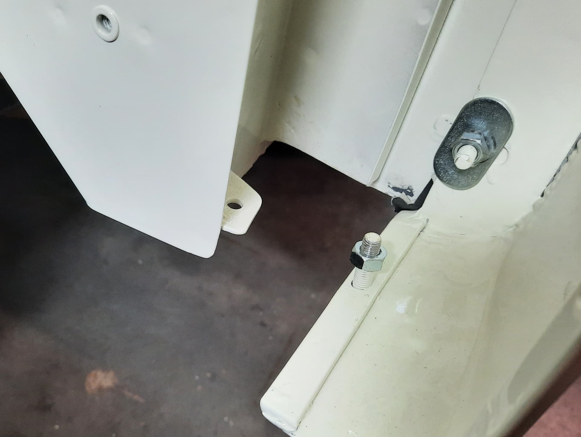
My 1954 XK 120 OTS has a vertical 1/4" UNF stud welded to the inside of the wing at that particular position. There’s also an angled bracket with hole welded to the B-pillar construction. See picture.
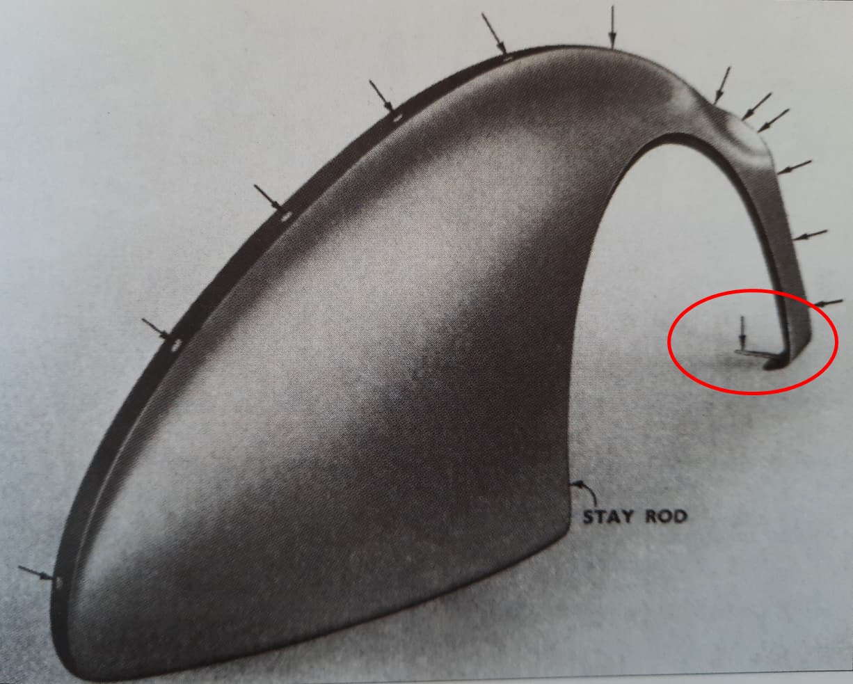
I couldn’t find any information about these strips as nothing is mentioned in the XK 120 SPC (nor the XK 140 version). Urs Schmidt (Volume 1, page 233) shows a works photo from the Service Manual, that (indirectly) refers to this bracket as it is one of the connections that holds the Rear Wing in place.
The photo shows some kind of bracket fitted to the inside of the Wing and the arrow most likely indicates that the bolt at the body side of this bracket will have to be removed. This drawing might also implicate that the bracket was (initially?) welded to the inside of the Rear Wing, which might be the reason there never was a part number for these brackets.
Had a look at other (later) XK 120s and for example Tadek’s disassembly photo site shows some examples of such a strip. I think I can see a nut (or bolt) on the inside of the wing as well.
The only reference I found so far is from Bill Basset mentioning Fender Stays (Forward Lower Rear) - XK120 but unfortunately without a picture
I will have to make a strip myself (which isn’t that complicated) but still looking for more input. Any XK Lovers with more details?
Bob K.
Addition:
The text on Page N.37 of the Service Manual (on which Plate N.23 is shown) reads: : Remove … the nuts and bolt from the front stay. Emphasis is put on Nuts (multiple) and Bolt (single) meaning there was one bolt and nut (body side) and one single nut (on the 1/4" UNF stud welded on the Wing).
So my assumption that the bracket might have been welded initially seems incorrect.
Mine are held by two 1/4" screws and nuts. The material is 3/4" wide, 4" long and about .080-.083" thick. The 1/4" holes are spaced at 3.25" and 3/8" from the ends.
What surprised me was that it is welded to the door sill panel, so the one screw seems unnecessary. I’ll check the other side to see if it is different.
The other side is the same, welded and also with a screw into the door sill. I don’t know why.
The screws are 1/4 BSF 1/2" long hex head, the usual AUTO D marking, with a flat washer under the head and a helical lock washer under the nut.
Thanks for the info Rob. Don’t know why yours are welded on the body side; mine (and Tadek’s) have a bolt on that side (as well).
Also the Service Manual had a bolt on that side so “the jury is still out” regarding what’s correct…
Your bracket dimensions are very close to what I had drawn to fabricate myself. Thanks again.
Bob and Rob: Mine appears to be like Tadek’s car. The outer setscrew (AUTO R) comes up from the underside with the nut on the top. The inner setscrew (BEES) comes down from the top with the nut on the bottom.
My car is two years after Rob’s and three weeks before Tadek’s. I didn’t see any signs of welding.
S 681273 from December 1953 is a super original and well-documented car. The photo below appears to show that the outer fastener is a setscrew not a stud. (Although unlike Tadek’s and my car, it comes down from the top with the nut on the bottom.)
related to the wing install…note that certain fixing bolt lengths along the arch of the wing to body are different lengths. Shorter ones are needed in certain places. Too long a bolt will dimple the car body at the arch. There is a service bulletiin about this…I do not have the number and text of that at hand. Also the rear wing fixing rod is adjustable --has an adjusting nut, and this changes the position of the lowest part of the wing aft of the tire, I have never seen a spec for this–seems the lowest part is vertical…it also changes the space from tire to wing–so that the tire is inside–so as to not make contact with the lower parts of the wing edge in the arch
Nick
Nick, I’ve often thought that the flat fender stays in front of the rear tires should have been drilled with at least one oval hole (instead of two round 1/4 inch holes). That would seem to allow for easy alignment of the bottom of the fender with the bottom of the door. Many XKs I’ve looked at are somewhat out of alignment at this point.
I know you have a collection of Service Bulletins. If you could find the one dealing with the front or rear fender stays, it would be of interest to me.
I believe I have found the flat steel part for in front of the tire.
BD.4709 Steady Plate
FS.104/4D screw (1/4BSF x 1/2" long)
FW.104/T 1/4" flat washer
C.724 shakeproof lock washer
FN.104/L 1/4BSF hex nut.
The surprise is the fastener quantities are 2 rather than 4 in both the OTS and FHC books.
Also these parts are missing from the DHC Supplement, which is usually the most accurate of the three books.
Looking at mine more closely, it seems to me that the screw is too short. A 5/8" long screw would be better.
Regarding the bolts: the first three from the front are the longer 1" ones BD.2401/2 followed by the four shorter 3/4 " versions BD.2401/1. The subject has been discussed before and the description in the SPC’s as rather “confusing”.
I just put the Steady Bars BD.4512 & 13 in a way that I “liked” as indeed there is no clear description what is correct and what’s wrong. See picture: But I guess this was more important for disc wheel cars with the “spats” in place that should be able to hinge in a proper way.
Yes, I saw that “Plate” BD.4709 as well, but I concluded from the context that this Steady Plate was the angled bracket for one end of the Steady for Wing parts BD.4512 & 13. If the “front steady brackets”, I was looking for, are fitted with a bolt and nut from the underside of the wing, then the “angled bracket” of the Rear Steady bar might also have been fitted using a bolt and nut. That would also explain the quantities mentioned. But there’s also evidence that this angled bracket was welded to the inside of the rear wing. See Tadek’s picture which is identical to my rear wing (my car’s only 5 months younger than Tadek’s). So Rob, you might be right…
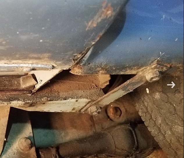
I found another pair of pictures from Tadek that actually shows the hole in the rear wing at the front for the “front steady” and also that the “steady” is positioned at the underside of the rear wing, just like mentioned by others. Also note the hinge pins on Tadek’s disc wheel XK 120.
I think the BD.4514 is the one to the rear of the tire. It was designed at the same time as the BD.4512 & 4513 steadies for the OTS, consecutive drawing numbers.
The FHC and DHC have different later part numbers for the steadies but the same bracket welded to the rear wing. I suppose this means a shop could have ordered the brackets separately for repairs. Difficult to guess whether a replacement rear wing would have included them.
After examining my car carefully in good light, I was convinced that the welds on those braces I mentioned were old repairs to the sills probably due to jacking there.
So I ground and chipped the welds and removed the braces. The welds were pretty poor, not factory work. So I withdraw my suggestion that the braces could have been welded. I also was able to make a better measurement with the micrometer, so I amend the material thickness, make it .075" or 1.9 mm now.
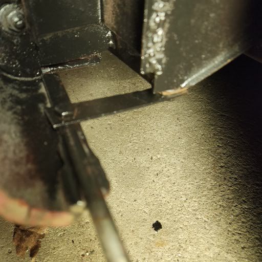
These are possibly the four setscrews (cleaned up) that fastened the flat braces in front of the rear tires on Tadek’s car. The photo below appears in the same general area as the front flat braces in Tadek’s photo album. If so, they’re the same as on my car, which is three weeks older. Two Auto R and Two BEES.
It suggests the front flat braces were attached in two separate steps. First, the outer sides of the braces were attached to the fenders. Later, when the fenders were attached to the body, the inner sides of the braces were screwed on using whatever branded setscrews were available that day. This might help explain the photo appearing in Urs Schmid, Volume 1, page 233.
That’s Plate N23 in the Service Manual.
Does the brace go above or below the rear wing edge?
Mine were above.
Looks like we have old photos showing both.
Agree with you that we see both above and below the wing at the front. I assume that this Plate BD.4709 was used after the doors and the rear wing had been placed on the body and that a certain adjustment was required to get these two aligned. As there were two holes and the Plate + bolts were picked by the operator, he (or she?) had the “freedom” to place the Plate above or below the wing (or even one below and at the other end of the Plate above).
I think my bodyshop has taken the liberty to opt for the “above” position at both ends of this Plate and at the same time opted for a stud instead of a hole for the bolt. So not “concours” but I’m happy with that as in this way the bracket is not so much exposed to the elements.
I also noticed that if you have a fixed distance between the holes in the Plate, there actually is very little space to move the lower front section of the rear wing in order to match the door. Tadek’s photos (see above) also shows a Plate that might have been bent to obtain the correct distance…I think I will put one longer hole in the Plate to give myself more room for adjustment.
I do not recall a TSB about the fender stays. I referred to a TSB about the bolts attaching wing to body being of different sizes: #88 —an 51, it has been found that on some…bodies…metal screws of unsuitable lengths…protrude into the wheel/tire area and can contact the tire. It does not mention the differing lengths of the bolts along the attachement bead–and that LONG ones used where short ones should be will dimple the bodywork.
Nick