My 1954 XK 120 OTS apparently had a (minor?) accident at the LH front that caused some deformation on 2 parts of the steering mechanism.
One of the Steering Tie Rod assemblies (C.4726 or C.4727) is slightly bent at one end over about 10 degree (?). This is only in one plain; the other plain is perfectly straight. See pic.
Has anyone tried to repair a similar item? Replacement is of course possible but only as a pair and cost around € 200.
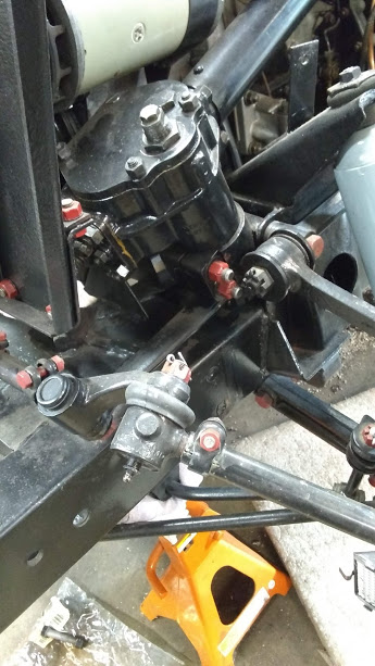
The other damaged item is one of the Track Rod Ends C.4135 or C.4136. See pic. This part is no longer available and therefore has to be repaired. First question is which Track Rod End still has the correct angle and the second is whether we should bend it back using heat?
The one on top is correct, the lower one bent.
Mark V is the same parts.
Only one of these three replacement shafts fit, the 14-1024, and I had to file it down on the OD to fit. The others were way oversize.
With the car all together and sitting with full weight on it’s wheels, the ball joints in the dogbone should be reasonably straight.
Thanks Rob and Paul!
Paul, I’ll give it a try with the flame.
Rob, it corresponds with the “accident damage” where by the angle of the arm has been pushed “flatter”.
Are these replacement Shafts from various suppliers having different diameters?
Other repair kits supplying a Shaft (or “Pin” ) with a “steel cased Polyurethane rubber insert”, refer to the availability of two versions: one for the XK 120 with a diameter of 0.91" (or 23.1 mm) and a “Mk 2” version with a larger diameter of 1.002" (or 25.4 mm) whereby in case of any damage to the original hole, it could be reamed to the next diameter.
Yes, that’s the idea, in my picture above I have the Mark 2 version and two from XK’s for the 120. I used the standard size 14-1024, and even that was oversize a little bit.
Further to the above messages regarding a damaged Track Rod End, I can now report that everything has been solved. The bent Track Rod End has been corrected using a flame torch.
Another (related) problem was that (due to the accident) the tapered hole of the Ball Joint had become oval at one side and I didn’t want to use it in this state. Replacements are almost impossible to find and I therefor opted for a solution using an insert that forms a new tapered hole. I discovered that this solution is often used in the USA (hadn’t heard about it in Europe).
The insert is placed in a hole of ⅞” (22.2. mm) drilled right through the heart of the existing tapered hole.
As the length of this (universal) insert is “oversized” it was too long for this Jaguar XK application, and had to be cut to size.
The result is good, but the Ball Joint is now about 3/16” or 4 mm higher compared with the standard version. I guess this is not a real problem given the distance between the two Ball Joints of 9” or 229 mm of the Steering Tie Rod Assembly (which leads to an angle shift of 1 degree).
This is all based on the ⅞” hole mentioned in the instructions, but some simple calculations learned that a hole of 23.0 mm would allow the tapered section of the Ball Joint to end up about 4 mm closer to the Track Rod End.
Further to your earlier information.
The Track Rod Ends C.4135 and C.4136 consist of a center bush with an arm at one side and the threaded end at the other. One has LH thread and the other RH thread. So far everything clear.
But the arm is (in vertical direction) not in the center of the bush and the bush is therefor at one end taller than the other end. See picture below:
That should determine (as far as I understand the construction) which Track Rod End is on the LH and RH side of the car. It is unclear from the SPC which casting number (140-152 or 140-153) is the RH or LH version (resp. C.4135 and C.4136).
Cannot find any good image in the “usual” documentation including XK 120 Explored.
Bob K.
PS. The Steering Tie Rod Pin replacement (supplied by Coventry Auto Components Part No. 4247) fits straight in the existing hole (with some pressure)…
The complete assembly is now ready including new Tie Rod Pins. The Track Rod ends C.3493 & C.3494 just needed a few hundreds of a millimeter removed for the Tie Rod Pins to fit (with a good press fit) for which my Dremel with a cylindrical sanding band was fine. Just a bit of paint will finish the job. Thanks all for your input.
The modern replacement versions are so designed that the tapered end turns within the Tie Rod Pin (which is pressed in the Tie Rod End). When I tightened the nut of my new Tie Rod Pin, I noticed that the tapered end could turn within its metal casing. I understand that within the casing is now a polyurethane layer to absorb vibrations whereby possibly some grease has been used (but in any case “sealed for life”).
The original versions had a different construction. The Tie Rod Ends were supplied with the “Screwed Pin” in place whereby a rubber bush around the Pin was bonded in the Track Rod End.
Don’t know whether the rubber had to absorb the turning movement of the Pin or that the Pin could turn (freely) within the rubber. See also the photo above shown by Rob R. in his earlier reply.
I started this thread with a photo of my damaged Steering Tie Rod End assemblies (C.4726 or C.4727) that had to be replaced as also the ball joints were “shot”. New ones are available but far from cheap GBP 200 to 300. .
I decided to make them myself, using the earlier adjustable version C.3070 as a basis but without the adjustment option (which was deleted anyway in the later version).
The Ball Joints C.3062 and C.3063 are still available from Quinton Hazell, (QR205LHT or RHT but also as NOS in the original version with grease nipple). If you’re lucky the latter can be found for prices around GBP 10 to 20.
I used a piece of steel tube that fits tightly over the 11/16 UNF ends of the Ball Joints: steel tubing is available in the dimension Ø21.3 x 2 mm fitting perfectly. With the ball joints positioned exactly 9" centre to centre, I first placed 2 pins per end and later welded the ends of the pins to the tube for “just in case”. I’m pleased with the result. All I have to do now is paint them black.