I’ve assembled the clutch fork shaft in the bellhousing now, having gone with Coventry Autos’ bronze fork, shaft and tapered pins. Fit seems to be OK, slightly offset fork but that seems to be normal.
A question: Obviously the pedal shaft that runs to the chassis is installed after the engine and 'box have gone in. My car is RHD, so I have the correct shaft to fit on the right side of the car. This leaves the LHD hole on the left of the bellhousing open. Did Jaguar fit any kind of simple blanking plate to this (either side)? Not sure I want the English weather filling up the bellhousing any more easily than it already can.
I don’t believe Jaguar fitted a blanking plate to the hole on the left of the bellhousing. However, a nicely-made one would certainly do no harm. I’ve considered it myself.
Thanks Chris, seems sensible and wouldn’t take long.
Jaguar did not put anything in there for RHD nor LHD. Yes, your chassis will fill up with road dirt. A plastic plug on each side makes sense.
Hi.
I recently had the engine and box out of my mark 9. I didn’t do anything to the clutch fork or operating lever assembly. However, now that it’s all back in I regret no check-in these bits out more carefully, as the arm on the shaft that the push rod works seems not to be in right position for maximum leverage. It would appear to be pointing to far aft, as if, over the years the rod or fork has twisted slightly.
I wonder if you could please send me a photo of the position of the operating arm at the point that the release bearing just contacts the pressure plate so I can compare.
Ps. No sign of any bungs in the big holes in the bell housing, and nothing shown in the manual or parts book.
Thanks.
There are loads of holes in the chassis, Rob, I don’t think I’ll bother - just a large quantity of Dinitrol will be going in via the spray wand! It’s the hole in the gearbox bellhousing I’m referring to. I’ll make up a simple plate and fix with a couple of bolts.
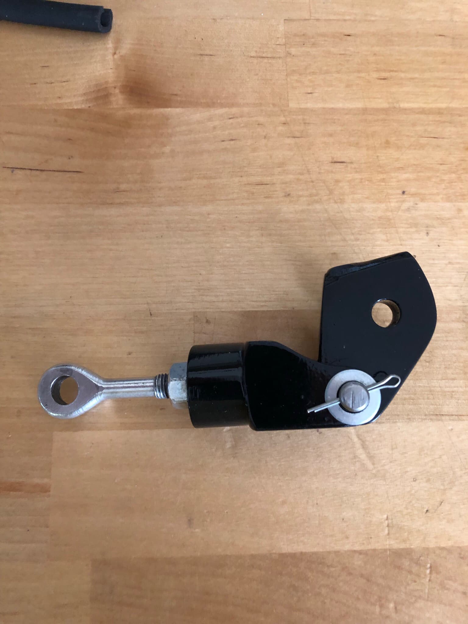
I’ll try and remember to get a photo, Wardell - I don’t know if the MkIX is the same as a 140 though. I noted that the new clutch operating lever on the clutch fork shaft is quite a bit longer than the one on the old shaft. I have a feeling that may be from a 150, as it has the full hex heads on parallel pins which I don’t think is correct for a 140. This car had a lot of starter issues before it was taken off the road in 1982, as evidenced by the saloon flywheel and Austin Healey-spec starter motor I found on disassembly. I’m not using the parallel pin arrangement as the pins are both loose in the shaft, so tightening them still leaves free play, unlike the tapered pins.
Edit - Wardell, I have converted to the E-type 9.5" diaphragm clutch with the deeper release bearing, so I don’t know that a photo of mine will help.
1 Like
Roger:
I assume you are referring to the hole in the bell housing through which the clutch operating shaft goes through, as opposed to the pivot shaft, which has it’s opposite on the other side for R.H. (or vice versa)? My L.H. drive XK120 has never had a blanking plate in my 59 years of ownership although I suppose it is possible that it had one that got “lost” in the car’s first ten years of life. As I am currently in the throes of removing my gearbox again (I’ll resurrect my original post on this when I resolve the current issue!) and everything is easily accessible perhaps I should make up a similar blanking plate to close off the housing. By the way, a brake wheel cylinder dust cover (suitably enlarged) fits over the housing for the bronze bearing on the pivot shaft to provide a good seal.
Chris.
I had to pull my transmission this spring to repair a broken fork (and subsequently rebuilt the gear box thanks to the help of everyone on this forum)!
The open hole bothered me as well so, I made a nice brass plate to cover it. Made me feel better!
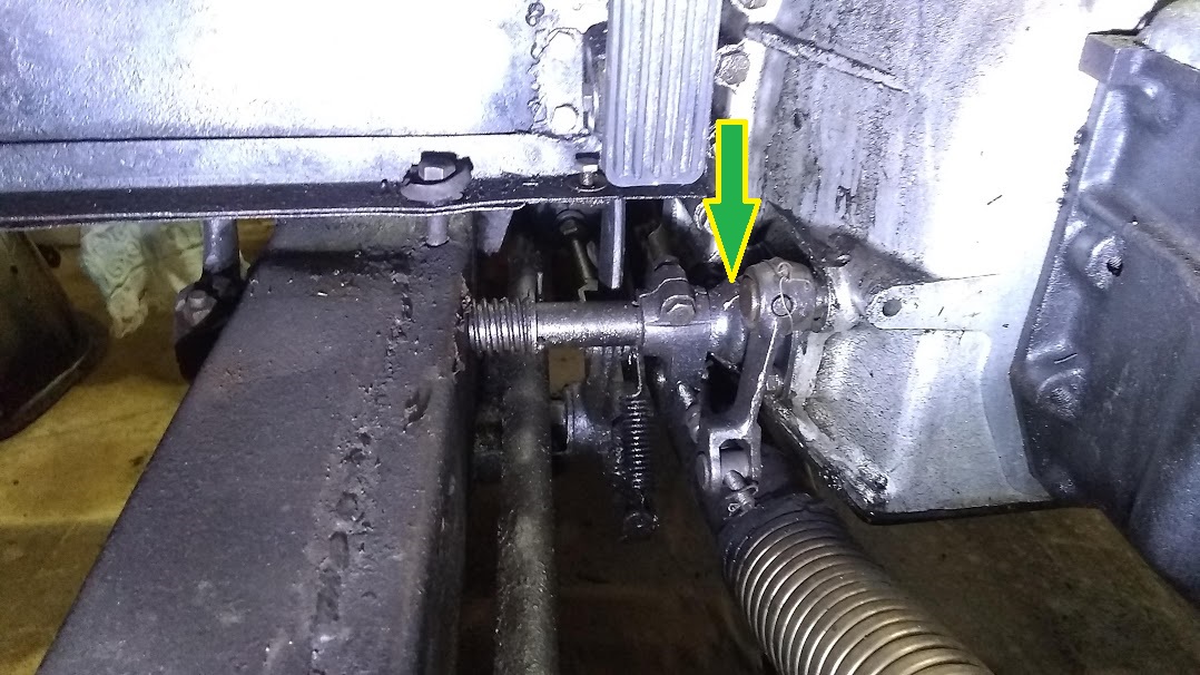
Not quite, Rob - although it depends which hole your arrow is pointing to. This is the now-redundant LHD clutch fork shaft hole:

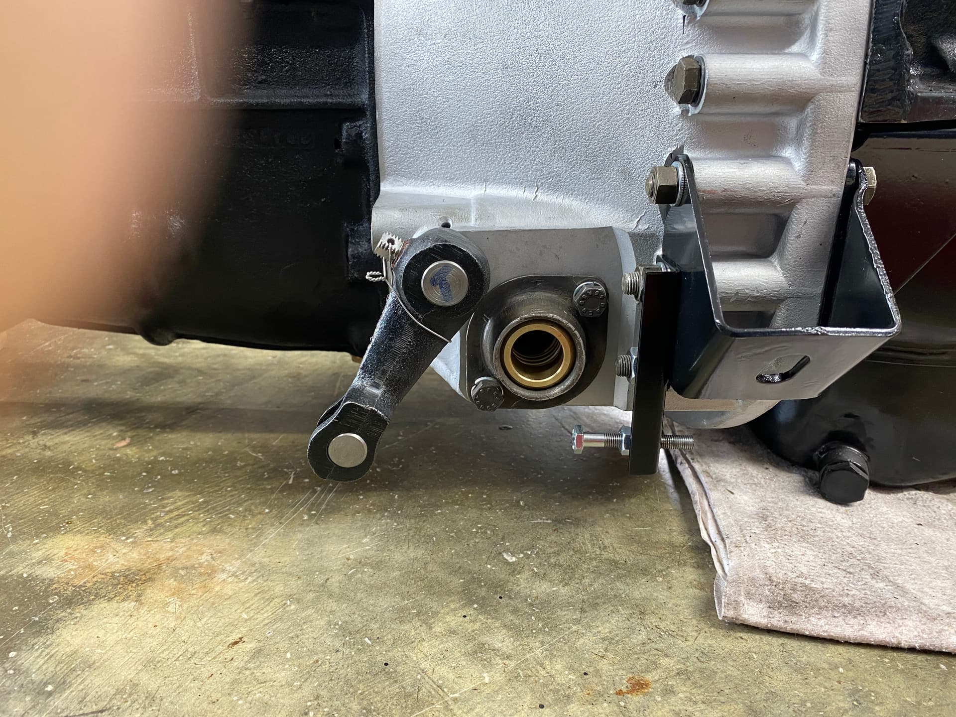
…and here’s the clutch fork external lever pushed into full contact with the clutch pressure plate, Wardell - but as I say, the clutch in this car is a 9.5" diaphragm type, with the deeper E-type release bearing, so the position of this lever will almost certainly not be the same as the stock XK140 lever.
Roger
Thanks very much for the picture, it’s just what I need.
I notice the lever is in about the same position as mine is. I find this a bit odd, as I would have expected it to be a bit more towards vertical so that the push rod pushes towards the center line as opposed to pushing past it. I don’t think that the different release bearing and diaphragm clutch make any difference, as the taller bearing makes up for the shallower clutch.
If you don’t mind, could you send me another picture when you have the slave cylinder and push rod installed and adjusted please, or are you using a no hydraulic, mechanical linkage?
Thank you once again.
I agree with Chris and Rob C that the factory probably didn’t supply a blanking plate for the opposite side of the bell housing not used by the clutch shaft. Thus, there is a large hole on one side of the bell housing that can be an entry point for water and debris.
It’s easy enough to make a cardboard template for the unused hole and then cut a metal blanking plate for added protection. The two holes are already factory-tapped into the bell housing to secure a blanking plate. If I remember right, they take 1/4 inch by 20 coarse thread setscrews. Probably .5 inch in length will work depending on the thickness of the home made blanking plate.
Mike,
Yes, we could close that hole at the non-used clutch shaft side, but the front opening of both the early and later bell housings are not exactly “sealed” with these simple steel plates with several gaps. And due to their position, these openings are acting like a kind of “scoop” collecting everything swept up under the car. That’s probably the reason why you find so much dirt when opening the bell housing.
Bob K.
Wardell, that will be a while away as the engine isn’t in yet. Also, yes, I’m using the original mechanical XK140 linkage. This will be a mirror image (RHD) of the photo Rob posted in post no.7.
Bob, the lower bellhousing plate on my 140 is a pretty decent fit with the bellhousing bracing brackets at the side. I doubt very much would get in through the redundant shaft hole, but it just seems untidy to leave such a large hole open when a simple closing plate would take 10 mins work to make, so I’ll probably go that route.
Chris, the correct seal for the bronze pivot bush is available from the usual suspects, C3323.
Roger:
Thanks, I just happened to have a couple of spare wheel cylinder dust covers “in stock”.
Chris.
Roger, I replaced my Borg & Beck 10” with a 9.5” diaphragm E-Type clutch. You will find that the diaphragm type reduces pedal effort slightly while providing greater holding power which actually increases with wear due to the action of the Belleville spring (~1200psi for the 10” vs 1600 psi 9.5”)
The diaphragm type requires less pedal travel to engage/disengage and consequently produces a less progressive application. I designed and made an extension which adapts to the existing release lever (with no modifications to the original parts and is completely reversible) to take advantage of this fact and have reduced my clutch pedal effort by 50% from original and have an excellent progressive application of the clutch.
Thanks, J E - would you have a photo or info on your modification?
1 Like
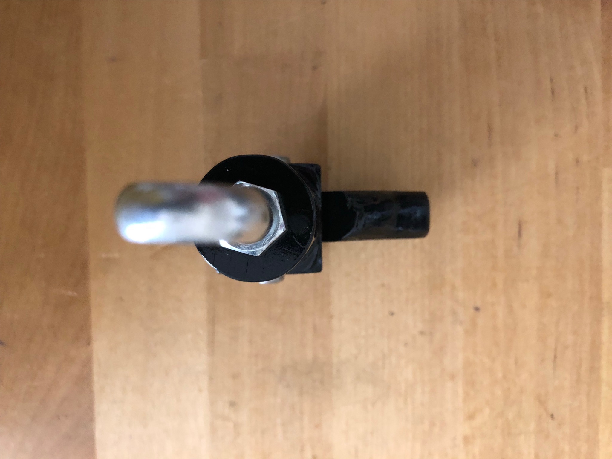
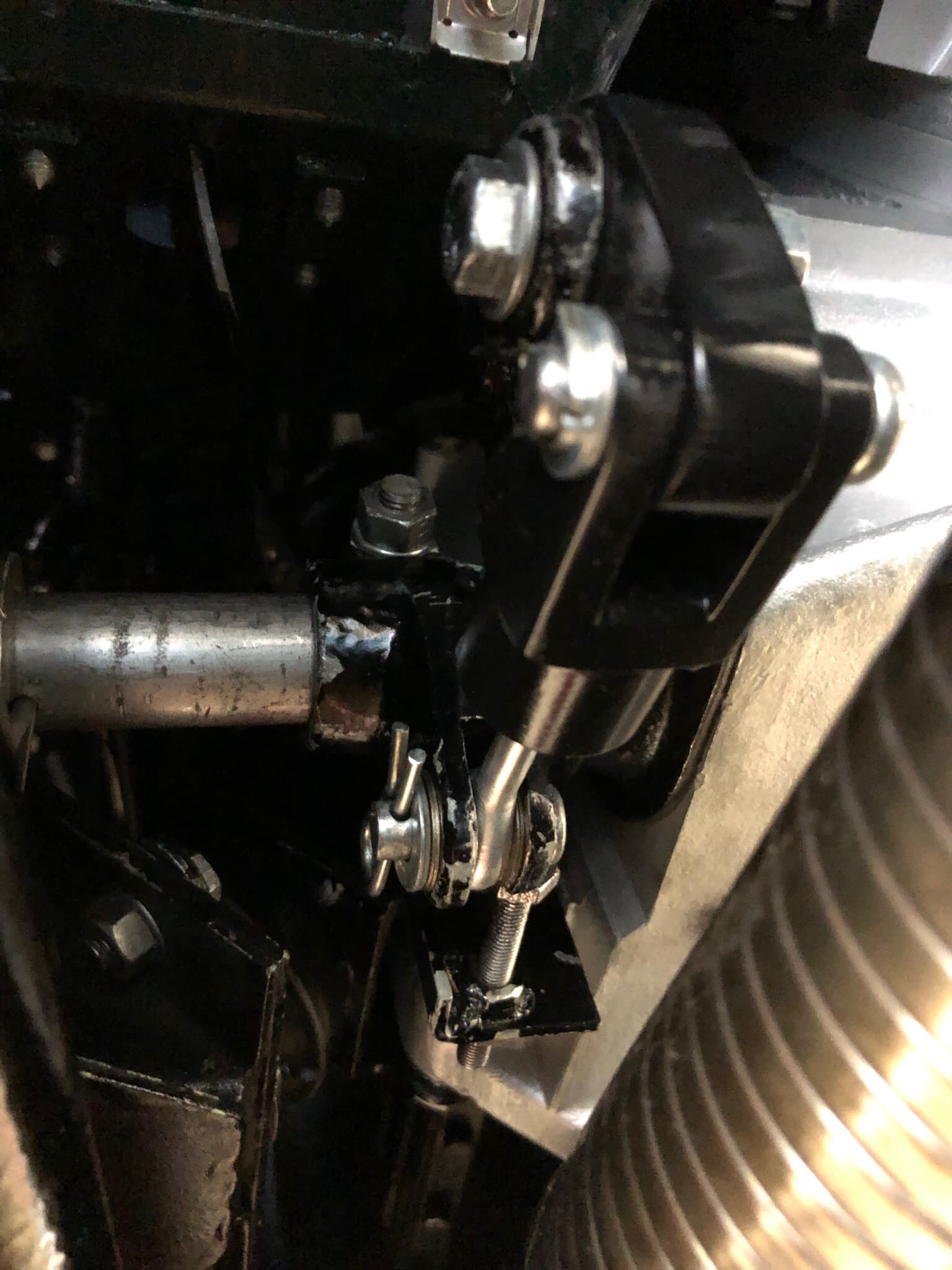
Roger, here are a few photos of the pieces and on the 140. On LHD cars there is possibly a exhaust head pipe clearance issue if the engine mounts have settled, I replace all 4 mounts while I was replacing the clutch with updated mounts with the steel cups on top to prevent the rubber from bulging out over time and causing the engine to drop, with the flex sections in the head pipes the exhaust can get very close to the clutch pivot arm. The cross bolt, washers and locking nut as well as 2 specially made 5/8” (16mm) OD X 5/16” (8mm) spacers for the pivot end of the release lever to center and lock the extension arm in place are not shown.