That’s a great bit of design, thanks for the details. Did you use the standard threaded rod cut down?
I presume the ‘flat’ top of the extension prevents rotation within the release lever. Spacers I can turn on the lathe, but do they have any special features to lock the extension arm?
My car is RHD, so no exhaust issues.
I’d think the dropped angle would make the pedal lever work in a more effective arc.
Roger, Yes the flat top prevents rotation. The 5/16” (8 mm) holes in the extension are 1.25” (32mm) center to center. The rod, a replacement, is a shortened version of the original which I kept intact. The material for the extension was precision ground bar stock which I had and is thicker than standard cold rolled so it fit snugly between the “loops” on the end of the release lever. This as well as the thickness of the spacers is important because once the pieces are in place and the through bolt Is tightened you want as little lateral force as possible on the “loops” of the lever to prevent cracking. The forked piece was made of similar material and the overall length really needs to be determined by the current angle of the release lever with allowance for free play and future adjustments. To adjust simply loosen the lock nut, remove either of the 5/16” clevis pins and rotate. Not quite as slick as the original design but it gives one the opportunity to put some lubricant on the clevis pin which is often neglected. Regards, Jim
I do like that, it looks like a good addition to help make the clutch more progressive. However I don’t possess the workshop equipment to make the new forked piece, which wouldn’t be quite so precise if made with saws and files from a solid block. I’ll have to see how I go with the standard parts and investigate further if the pedal is heavy.
Hi Jim,
I have an NOS 10" early E Type diaphragm clutch in my 52 120 FHC, with an E Type clutch release fork. It was a direct bolt up installation and did not require redrilling the flywheel, as the 9 1/2" does. I am not impressed with the geometry of the adjustment rod (although it works OK) and your fix addresses that. Can you upload a picture in situ looking directly at the face of your new parts to show that new geometry? Thanks!
Tom Brady
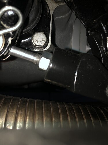
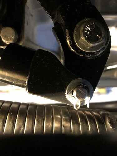
As I originally mentioned the clutch pedal effort was less with the diaphragm pressure plate but the progression of application was more suited to a car to be driven on a race track. The combination I arrived at gave me the progression of application identical to the original Borg & Beck pressure plate but with much less effort. Admittedly there was some trial and error during the development, the extension piece was the third attempt and all of the pieces were hand made. Drill press, bench grinder, vice, hacksaw and files are the extent of my “machine shop”. Given the proximity to the chassis and torsion bar these are the best profile photos I could take, the LHD cars have the exhaust to contend with, it looks a lot closer than it actually is ~ 3/4” (19mm) clearance the pipe runs slightly inboard of the lever.
Ah, that’s encouraging - I can do files and hacksaws pretty well.
Was there any particular reason for not welding an extension to the pedal lever? I would guess it was due to the need to change dimensions during experimentation, but now you have the result you want wouldn’t a good weld be a better bet than the bolt and nut?
That’s assuming you still have a steel lever, obviously. I’m fitting one of Coventry Auto’s steel replacements as my original is badly worn, and the usual suppliers’ levers are all aluminium, as far as I can tell. I don’t have the exhaust problem as mine is RHD.
Edit - I suspect not strictly necessary, but it seems neater:
Neat job, Roger! The odd drop of oil down the little hole is seldom done, I suspect, but a good idea if you can get to it…
Hole cover looks like what Jaguar should have done. ![]()
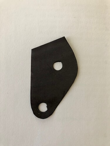
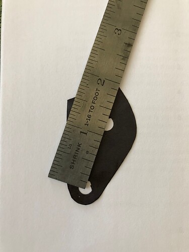
Welding would be a good way to do this I felt compelled to not modify any of the original parts permanently because it is a matching numbers car. I did consider making an entirely new lever or the possibility of a longer lever? from a Mk series car? Below are photos of the pattern used to make the extension. For scale the two holes are 1 1/4” (32mm) on center.
When mounted to the lever the shape of the piece creates a dog leg in the assembly which is necessary to achieve the motion required, from the center of the shaft where the arm mounts to the center of the hole for the clevis pin is 4 1/16” (103mm)
Really helpful info, thanks.
My car is very original and matching numbers (apart from the elephant in the room that is my RHD conversion), but the lever on the pedal shaft is badly worn despite a warranted 70,000 miles only. The hole for the pivot pin is badly ovalled and the pushrod has been bent at some time so has worn a groove on the inside face of the fork. Therefore, I am using a new replacement lever anyway. If I weld the extension, I think I could adapt one of the proprietary Girling/Lockheed clutch forks to operate between the two levers. Time to experiment, I think.
Well, not yet - I need to get the engine and 'box back in first…
Did you get your new lever from a reputable supplier?
There are some rubbish ones doing the rounds.
I bought a new lever from SNG Barratt, but realized after some time that it was made of aluminium rather than the original (presumed) steel. Preferring to stick with the original specification, I have now bought one from Coventry Automotive - I think Stuart is the only supplier making these in steel.
This is why I was asking. On this forum there are reports of the rubbish metal ones failing, despite being sold by ‘name’,suppliers. At lot of torque is applied to this component.
Hi Roger:
May I ask where you sourced your tapered pins? The reason I ask is that I have, unfortunately, experienced not one, but two tapered pin failures within the last year. I retained the original 10" clutch (new) following a gearbox rebuild, however, first the pin securing the clutch lever sheared and then, after that was rectified by drilling the arm to accept a nut and bolt, the one securing the throw out bearing fork let go. I currently have the gearbox out, again, and while I have a couple of new tapered pins from CAC I am considering the upgraded shaft and pins they offer that have the square shank as opposed to the taper. Stuart at CAC informed me in an email that this would resolve the pin shearing issue. Regrettably, while I generally keep meticulous records with respect to expense outlays on the XK, I cannot find an invoice for the pins. They came from one of the usual suppliers, but if I had a record (or my memory was better!) I would contact them with respect to the failures.
Chris.
My pins came as part of a set from CAC - pins, fork and shaft and lever.
I have an old set of parallel pins with a short lever, so presumably from a 150. The pins are not a precise fit in the holes, so there is unwanted movement in the mechanism. I don’t see how a parallel pin can locate better than a taper, as they are no longer and don’t extend into the other side of the lever/fork. Stuart didn’t have any stock when I was looking, either, so I stuck with the 140 tapers. The 9.5” clutch should be a bit easier on the parts too. I’ve only just got the engine in, I don’t want to take it out again!
Sorry to hark back to this, but I’m just doing final checks before fitting, and the dimension from the centre of the shaft hole to the clevis pin hole is 65mm on my lever. Is yours really 103mm?
Just making up the correct extension now…
Oops!
All done and dusted, and I can confirm this mechanism modification makes for a very nice feeling clutch pedal.
J.E.Farr, could I ask how you adjusted up the clutch throw and pedal? With your mod I have plenty of adjustment on both pedal stop at bellhousing, and in the pushrod between the two levers. The XK originally had the three-finger clutch cover with coil springs, with the manual asking for 1" free movement at the pedal. This seems a lot for a modern diaphragm clutch - what clearances did you use?
Roger, as far as adjustment is concerned the main thing of course should be adequate clearance between the carbon surface of the release bearing and the ring on the pressure plate to avoid constant contact. You may find that there will be slightly more free movement of the pedal because of the ratio change due to the modification to the slave lever. You can set the stop adjustment and your adjustment rod C2423 to maintain that clearance which will also determine your pedal position. I found that set the engagement/disengagement in the middle 1/3 of the full stroke of the pedal As a personal preference I was also able to move the pedal itself in relation to the main pedal lever forward 1/2” (13mm) to align it more closely with the brake pedal by machining an additional notch in the rod where it clamps to the main lever. This is something you may or may not want to do based on your personal preferences once you have it back on the road. I have been following your progress and it is looking great. Regards, Jim
Is there any reason not to use an annular hydraulic throwout bearing on a Tremec 5 speed conversion? Seems to me that it eliminates an antiquated and inefficient system. I have used these on many other conversions and they work brilliantly. Great feel and less pedal travel required with diaphragm clutch and hydraulics. It is way more efficient than the 150 method of using a slave cylinder to actuate the mechanical system.
Hi Bruce,
Sorry, but in my view plenty of reasons, based around the difficulty of servicing. I have worked on several cars (SBFs, not Jags) with internal hydraulic clutch release bearings and fixing a simple leak is a royal pain. A simple mechanical rod and lever mechanism is simple to fix - the exception being the terrible Z-bar of the early Mustangs, but there’s a nice cable option for that.


