The other end joins in with the main harness to the sending unit and goes into the main harness to the trunk.
The other end of that grounding wire must be a grounding point somewhere in the trunk. Perhaps it’s the same one as for the tail lights. It’s not on the wiring diagram.
Mocked up the fuel tank today in 112F degree heat. I wanted to make sure I was drilling the stud holes in the right places in the tray. It turned out that the builder of the tray had suggested the right places. If you look at the second picture you’ll see holes in the channels but they do not go through the tray. This exercise also allowed me to start with the right lengths of round stock for making the hanger studs.
With one terminal the resistance should change gradually with moving the float.
With the other the resistance should be zero when the float is down, i.e. empty tank, and then jump to infinity (open circuit) with moving the float up.
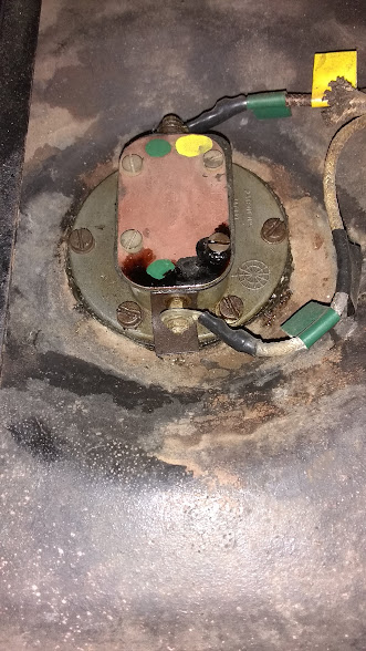
Green with yellow is the light circuit.
Green with black is the level sensor circuit.
As I recall, the float goes forward from the hole in the tank where there is plenty of swinging room for it to operate.
Hmm, it shouldn’t. Open it up and let’s see what’s inside.
There should be two wiper arms that move with the float arm (yellow and green arrows).
Both touch the sides of the resistor, wiping along it as the fuel level changes, and making a resistance ground with the green/black wire.
One (green arrow) touches the warning light contact arm (red arrow) when the float is low, and making a direct ground with the green/yellow wire.
I don’t have a photo, but there’s a brass bridge linking the low fuel light to the center terminal on the back of the fuel gauge. It’s fiddly to get it adjusted so the low fuel light functions.
Be sure to get it working before final installation of the instrument panel. If not, you’ll be laying on your back under the installed instrument panel with your test meter and tiny socket set. If the brass bridge isn’t connected properly, the fuel gauge itself will function normally, but the low fuel light will not come on.
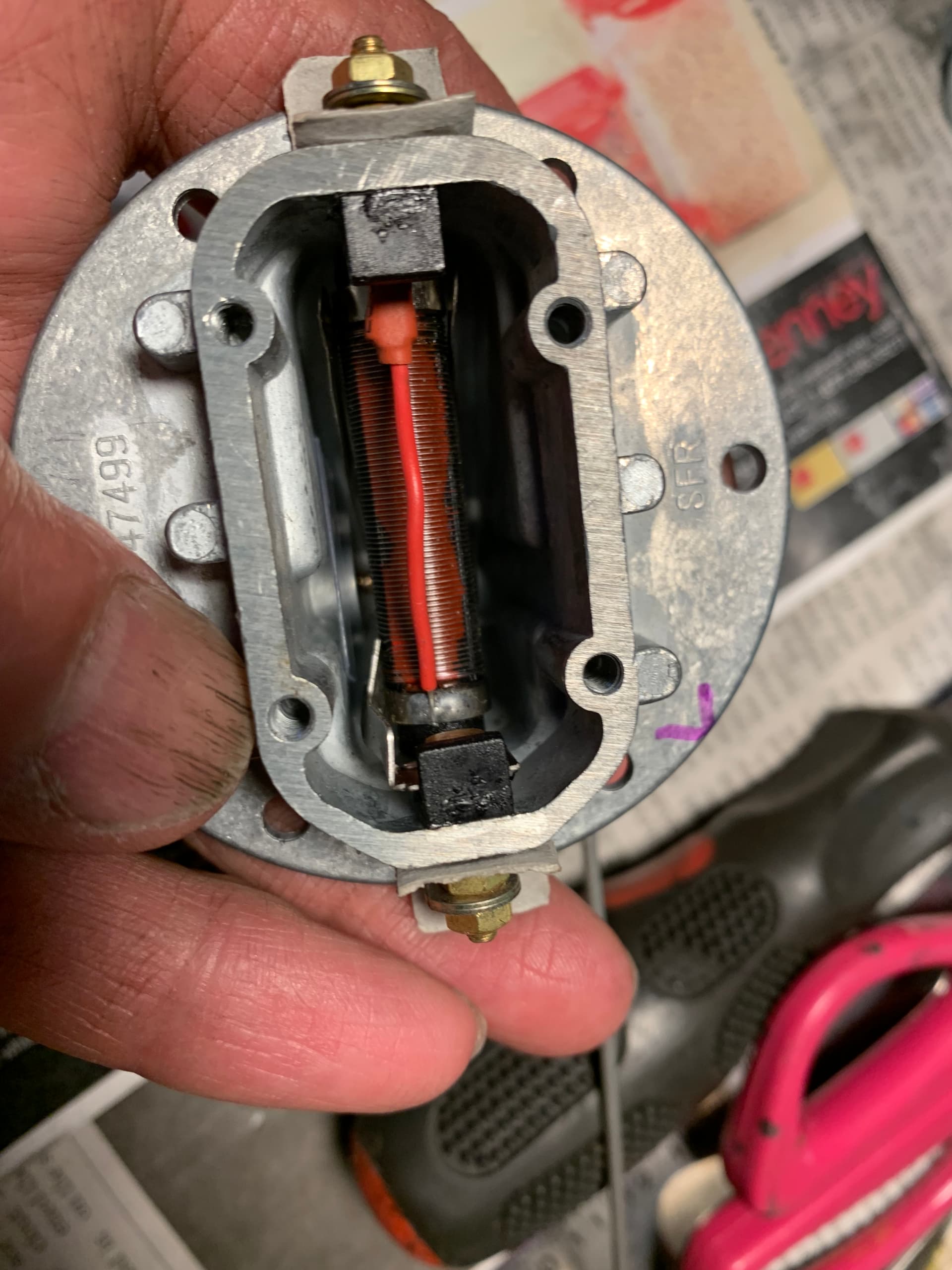
Alright, I’m studying this thing, and I marked up the components.
Yellow arrow is the wiper that drags along the resistor and should change resistance, thus operating the needle on the gauge.
Green arrow is the moving wiper that touches the fixed contact and operates the light. It does not appear to be touching the resistor.
Red arrow is the fixed contact that operates the light, connecting to green/yellow terminal where the green/yellow wire should be attached.
Green/black arrow is the external terminal where the green/black wire should go.
Red/brown blob is where the red wire is attached to the end of the resistor but not the green/black external terminal.
Blue arrow is where the resistor is attached to the green/yellow external terminal.
A-HAH! The red/brown blob and blue arrow are on the wrong ends.
Compare it with mine, where you can see the solder joint on the opposite end from my 3 arrows.
So I believe the maker has connected your resistor backwards.
Good analysis, Rob. Thanks. I’ll send it back and keep looking for another.
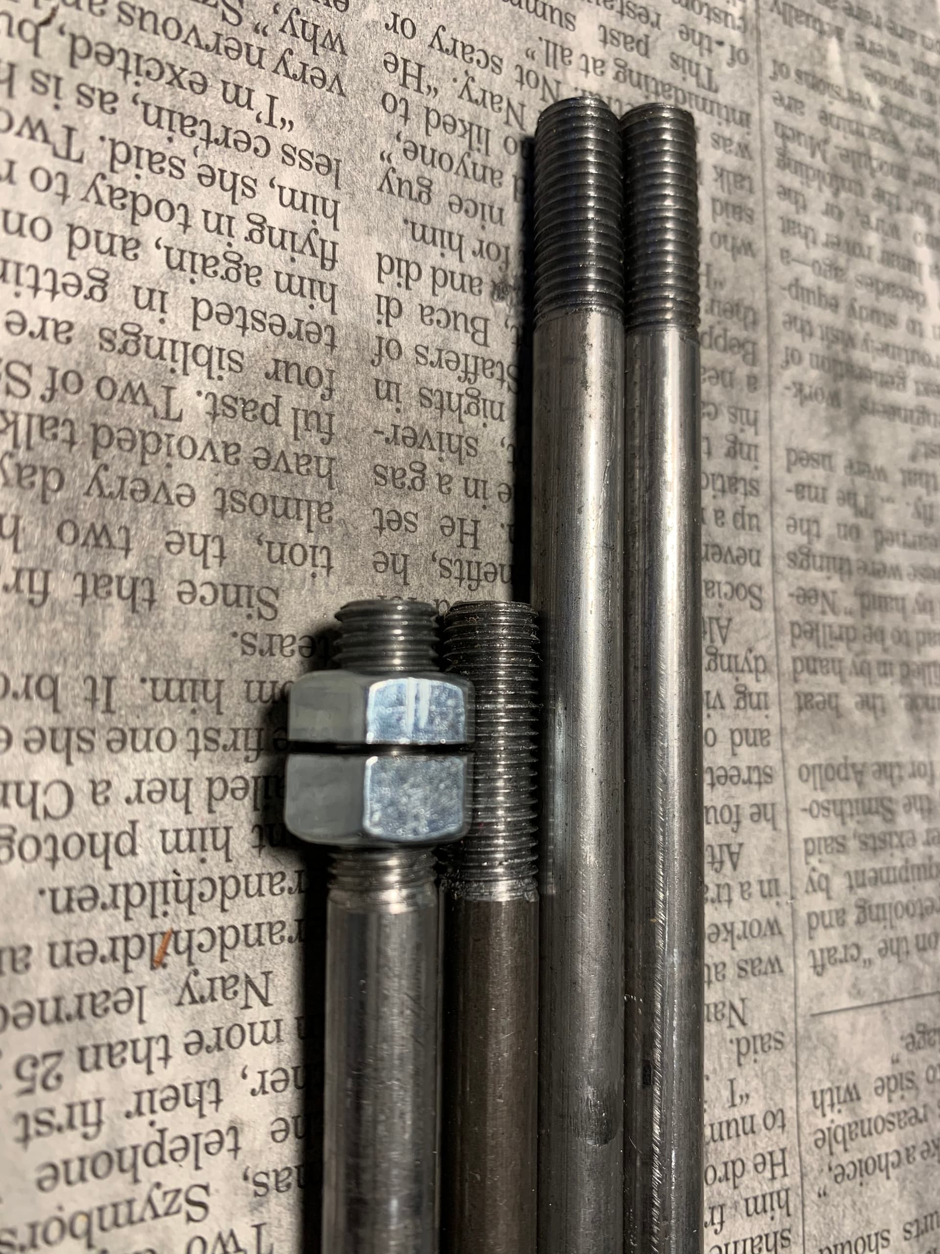
It started cooling off here and I’m making the hanger studs now. Bernard had measured 12-3/4" and 8-1/4". I made one of each and I’d say that’s just about right for my new tray. Both the UNF main nuts and the jam nuts are machined on one side. Not to be splitting hair here, but do the machined sides face each other when installed? Thank you.
Thanks Mike. Moss offered to send me another sending unit. I wished I had known about your NOS.
Let’s see if the replacement will work as intended. I made the studs and the nuts today based on Bernard’s measurements Mike Balch’s photo.