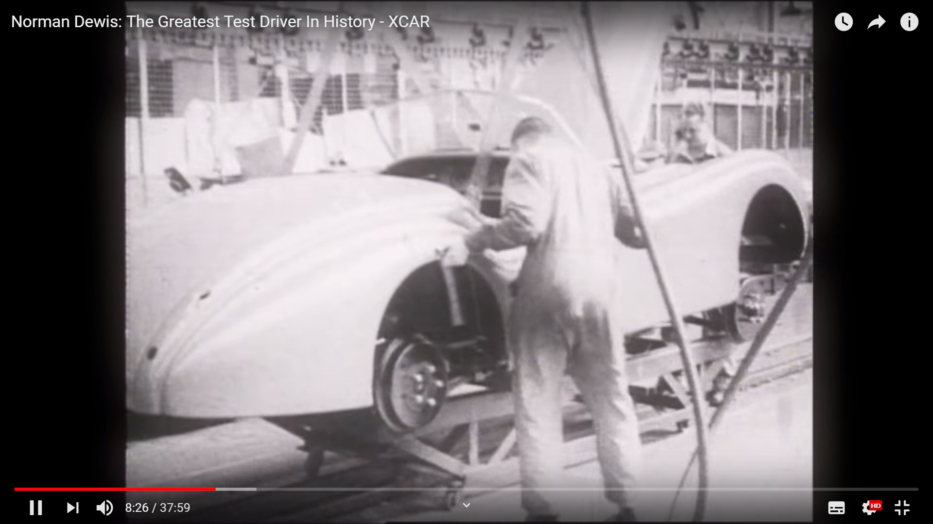
The new XKs/Moss XK120 140 150 parts catalog is published…available from them free for the asking…on website…exploded parts diagrams…and now includes prices: …and interesting production line 1948 aluminium body photo on cover,.,.is that Lofty or Sir W onlooking? what can you “see” on the XK bodys on the line…and the chassis on the line to the right? Should be out to you by now if existing customer… Nick
1 Like
The chap on the left wearing a lab coat with his hand on his hip is probably a line supervisor or inspector.
I think they are steel body cars; I don’t see the big rubber grommet on the windshield post.
On the far left are Mark V saloon bodies.
On the far right are an XK120 chassis followed by two Mark V chassis’s.
The 120 has the shorter carb dashpots, and must be a RHD as we can see the glass brake fluid reservoir by the carbs. I wonder what’s holding it up? Perhaps just the supply pipe? Or some temporary bracket?
I suppose it makes sense that they would get the brakes filled, bled and adjusted before putting the body on.
So with those clues, I’m going to guess the date as late 1950 or early 1951.
nice catch on the windshield rubber…tho the caption says alumin…in 48…likely incorrect., still early tho as .the parking lamp is not yet affixed. N.
can someone post the picture in question please:smile:
 with credit obviously to Moss/XKs…catalog is free…
1 Like
OK thanks well know photo I think
and this one…book cover…could be interestin read…by author who worked in the factory for years…
Noted.
Thank you.
…


Have only just seen this thread. It’s from a video, does the whole video exist?
I’m interested in how the body is supported - no visible bracing, doors are on etc.
Thoughts anyone?
Probably the doors themselves. On the OTS, there’s a clever dovetail that would do well enough for the short trip from skid to the frame.
Excellent, thanks Rob.
In the picture sequence above you can see four nylon slings. The slings would not necessarily be all the same length, might be two different lengths, so that the body would lift level, not tilted. There would have been a spreader bar above the picture on the crane hook, and some sort of hooks on the slings that would hook on under the upper valence in front, and somewhere around the convertible top attachment points at the rear. I’m not familiar enough with the OTS to guess exactly what they would hook onto, but keep in mind the top frame is not on yet. The lower valences are not on yet either. The steering column might be in and tied up out of the way, can’t be sure; I’ve often wondered about that. Electrics and dash are in, but not lights.
I speculate the steering column was, as you surmise, positioned up in the body before the body was lowered onto the frame. This is how I did it just recently and it went off without a hitch. I at one point before getting heavily into bodywork installed and removed the steering column with the body on the frame and it required pulling the lower front wing outward to clear. Even then it was a tiny bit of a challenge getting it in. Not something I wanted to do once getting the thing straight.
Yes, I too have removed and reinstalled the column on an assembled car, in this case an unrestored and not yet repainted FHC, and I could have used two helpers, one to pull the fender out and one to guide it through the dashboard, and I was 30 years younger. I think the guy that wrote the procedure in the manual never actually did one.