[xk] XK120 Chassis Drawing

I have restored/recreated the drawing number C6792 of the chassis frame
weldment, from the blueprint copy that David found in his car. The full size
blueprint copy he had was on ammonia paper from the 1960s or 70s, folded,
crumbled and faded on the edges of the folds and the sides facing out. I
scanned this one but it was too smudged and discolored so the scanner picked
up every little smudge and it was pretty much useless.
There was also a photocopy reduction, probably made from this blueprint
before it got faded, from which I was able to get most of the detail missing
from the full size print. Most of the lettering on this one was illegible.
Lastly there was a reduced tracing of the frame without any dimensions or
lettering and somewhat distorted in a few areas. I decided to zoom up this
one to 34" x 49" paper and then add all the dimensions and notes to it, as
the fastest way to get something useful.
So it is partly a restoration and partly a recreation. Like some of our
cars. :wink:

This is the C6792 chassis used on late XK120 FHC and DHC. The original
appears to have been drawn in ink on linen, as on the ammonia print I can
see what appears to be weave lines in places. It seems to have been a
tracing of the OTS chassis drawing C6692. The old drawing number C6692 is
crossed out and the new number written above it. There was a revision block
with revisions going back to 1948, but it was all illegible.
There is also an interesting note:
“with the exception of C5839 bonnet lock channel mounting plate being
welded on in position shown this frame assembly is identical to C6692”
This drawing is what we call a weldment, in that it shows part numbers of
every piece of the frame rails and where to weld all the little brackets and
bits onto the rails, but nothing that was bolted on. Surprisingly it does
not show weld sizes, but it does show certain suspension mounting holes that
were to be drilled after all the welding was done.
The original has a signature which was smudged but I believe it to be that
of Claude Baily the chief designer. I reproduced that signature as best I
could from an autographed dinner menu somebody posted on jag-lovers.

So if anyone wants a pdf file of this drawing, either 2.1 MB or 1.4 MB or
734 KB size, send me a private email and I will send it. Be aware of your
mailbox size, and your spam assassin may think it is spam. I found scans
smaller than 734 KB lost all the interesting detail.
Rob Reilly - 679187
Hi Rob,

Please send me the big one :wink:
Thanks for al the effort.

Christiaan van Nispen
Ex S680691
christiaan@vannispen.demon.nl

-----Oorspronkelijk bericht-----
Van: owner-xk@jag-lovers.org [mailto:owner-xk@jag-lovers.org] Namens
R_and_J_Reilly
Verzonden: dinsdag 16 maart 2010 13:38
Aan: XK mailing list
Onderwerp: [xk] XK120 Chassis Drawing

I have restored/recreated the drawing number C6792 of the chassis frame
weldment, from the blueprint copy that David found in his car. The full size
blueprint copy he had was on ammonia paper from the 1960s or 70s, folded,
crumbled and faded on the edges of the folds and the sides facing out. I
scanned this one but it was too smudged and discolored so the scanner picked
up every little smudge and it was pretty much useless.
There was also a photocopy reduction, probably made from this blueprint
before it got faded, from which I was able to get most of the detail missing
from the full size print. Most of the lettering on this one was illegible.
Lastly there was a reduced tracing of the frame without any dimensions or
lettering and somewhat distorted in a few areas. I decided to zoom up this
one to 34" x 49" paper and then add all the dimensions and notes to it, as
the fastest way to get something useful.
So it is partly a restoration and partly a recreation. Like some of our
cars. :wink:

This is the C6792 chassis used on late XK120 FHC and DHC. The original
appears to have been drawn in ink on linen, as on the ammonia print I can
see what appears to be weave lines in places. It seems to have been a
tracing of the OTS chassis drawing C6692. The old drawing number C6692 is
crossed out and the new number written above it. There was a revision block
with revisions going back to 1948, but it was all illegible.
There is also an interesting note:
“with the exception of C5839 bonnet lock channel mounting plate being
welded on in position shown this frame assembly is identical to C6692”
This drawing is what we call a weldment, in that it shows part numbers of
every piece of the frame rails and where to weld all the little brackets and
bits onto the rails, but nothing that was bolted on. Surprisingly it does
not show weld sizes, but it does show certain suspension mounting holes that
were to be drilled after all the welding was done.
The original has a signature which was smudged but I believe it to be that
of Claude Baily the chief designer. I reproduced that signature as best I
could from an autographed dinner menu somebody posted on jag-lovers.

So if anyone wants a pdf file of this drawing, either 2.1 MB or 1.4 MB or
734 KB size, send me a private email and I will send it. Be aware of your
mailbox size, and your spam assassin may think it is spam. I found scans
smaller than 734 KB lost all the interesting detail.
Rob Reilly - 679187

In reply to a message from R_and_J_Reilly sent Tue 16 Mar 2010:

Hi Rob how about printed copies suitable for framing?–
godfrey
pender island bc, Canada
–Posted using Jag-lovers JagFORUM [forums.jag-lovers.org]–
–Support Jag-lovers - Donate at http://www.jag-lovers.org/donate04.php

In reply to a message from R_and_J_Reilly sent Tue 16 Mar 2010:

Use for the drawing -

Anyone contemplating the purchase of a replacement chassis would be
well served to include a reference to the drawing as a part of
their purchase agreement with the fabricator. In addition, it needs
some more sophisticated specification of tolerances than are
present on the drawing; especially on the machined features.

I have had personal experience with the need to be able to more
precisely define what one is buying on so complex a weldment
than ‘‘exactly as original’’. There are persons who build things in
this world who should not be presumed to have the specialized skill
and knowledge to get this right on their own, however sincere their
intentions.

Karl–
karl
–Posted using Jag-lovers JagFORUM [forums.jag-lovers.org]–
–Support Jag-lovers - Donate at http://www.jag-lovers.org/donate04.php

Rob Reilly;

Please send the big one

David

I know a guy with a poster printer. I’ll see what I can do.

Mike Eck> Hi Rob how about printed copies suitable for framing?


godfrey

Right, Karl.
This drawing is not sufficient in and of itself to make a new chassis from
scratch. Nor did the factory intend it so. This ties into a question Brian
asked off line, as to how was this drawing used on the shop floor.
The little balloons all around it are part numbers of the individual pieces
that go to make up a chassis frame. Each part would have had its own
drawing, drawn by the Jaguar staff, which would specify the material
thickness and type of steel for that part. The parts would be stamped out in
a machine called a press with specially made cutting and forming dies. This
could have been at any small stamping shop.
The pieces came together at a company called Rubery Owen of Darlaston, where
they were placed on an assembly jig, clamped down and welded together. A jig
is like a big table with stop blocks, locating pins, toggle clamps and
access holes for the welding torch all over it. Since Rubery Owen had a
contract for 12,500 chassis frames, they would make a special jig for this
job. This drawing was provided by Jaguar to Rubery Owen in order to design
this welding jig, and for the shop workers to know where to place all the
pieces on the jig.
So the deliverable from Rubery Owen to Jaguar would be a frame conforming to
this drawing in every respect, except for some of the holes that are marked
to be reamed to close tolerances at Jaguar. Possibly they didn’t trust
Rubery Owen to get these right, or chose to do them themselves for other
production control reasons.
But the dimensions should be useable for checking a frame when straightening
accident damage or doing other repairs.
Rob Reilly - 679187

In reply to a message from R_and_J_Reilly sent Fri 19 Mar 2010:

Rob,

It was helpful for you to add the comments about the use of the
drawings, and the manufacturing process.

I expect that the chassis drawing you reproduced was an assembly
drawing - which would not be expected to include all of the
dimensional information as a stand alone source - and that here was
a detail drawing of each part, one per bubble, that had lots more
dimensions.

What was really sort of refreshing was the ‘‘kinder, gentler’’ aspect
of things at that time; the drawing clearly showed a lot of trust
of the shop as it was more aimed at showing how a correct part
might be built than trying to keep the shop from building the wrong
part that would be typical today in many environments.

I was charmed by the note that said’’ ‘‘Dimensions marked thusly :+:
are important and must be maintained’’; but absolutely no tolerance
specified.

Whilst that note is entirely appropriate for essentially internal
use by an experienced car building operation such as Jaguar, it
would never serve to specify a reproduction part from a supplier
with no way to appreciate the end use, and that was the point I was
trying to make. Perhaps better than sending them an old chassis
and saying make ten like this, but not much better.

When I asked about the tolerance matter, my ‘’ exact reproduction
chassis ‘’ maker responded by warranting that all of the suspension
parts would be test bolted up to fit, which gets to the issue of
Jaguar reaming parts at assembly, but when push came to shove, he
simply drilled out some holes way oversized so that things could be
made to go into place, and ‘‘drilled’’ is a kind word as many of the
holes were ovals.

My goal was to save others from this sad experience.

Karl–
The original message included these comments:

This drawing is not sufficient in and of itself to make a new chassis from
scratch. Nor did the factory intend it so. This ties into a question Brian


karl
–Posted using Jag-lovers JagFORUM [forums.jag-lovers.org]–
–Support Jag-lovers - Donate at http://www.jag-lovers.org/donate04.php

Hi Rob,
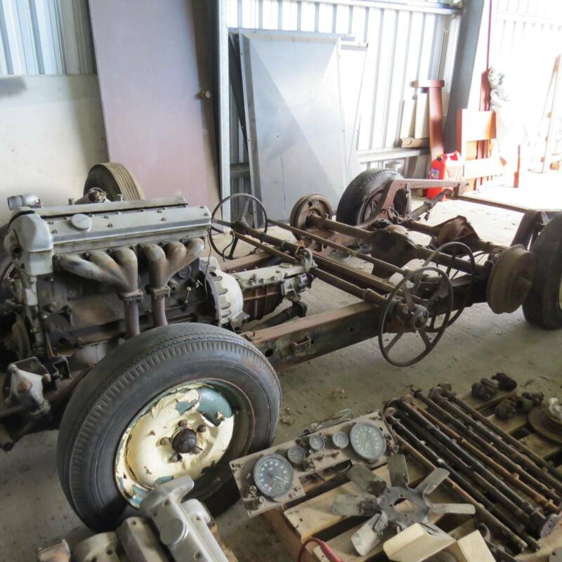
I have just bought a heap of XK120 parts including a rolling chassis, but I have concerns with it. It would be very helpful if you wouldn’t mind sending me your pdf drawings so I can compare.
My email is damoco@tpg.com.au. I’m in Windsor Brisbane Australia.
All the best
Dan (jagoz)

Rob,
Should have added this photo. Not the best, but will post more when I pick up the load in the next 2 weeks

Dan attached is the chassis PDF I would be interested to chat re the chassis to identify etc
regards terry Western Australia
0407797003
tmcgrath@bigpond.com
XK120_chassis_drawing_2220KB.pdf (2.2 MB)

Welcome Dan.
That looks to me like a Mark VII chassis, but missing the central cross bracing.
The bar across the tail end looks Mark VII.
The thermostat housing is Mark VII.
Steering idler also looks Mark VII.
Are there engine supports at the bell housing? I think I see one. Mark VII has them but XK120 does not.
Engine and gearbox look to be early Mark VII which is virtually identical to early to mid-range XK120.

Definitely looks Mk7. I have more experience with 7s that 120. What does the wheel base measure?

Hi Rob,
Can you please send a copy of the large file to me.
Caryyamamoto@gmail,com
I’m working on a 1950 xk 120. Thank you!

Cary,

Why don’t you use the PDF file as presented by Terry McGrath (see above entry of June 2019? This file is of a very good quality and you can zoom in where you want. However, it is the later chassis with some (minor) modifications w.r.t. your 1950 chassis.

Bob K.

1 Like

Yes, that’s the file. Scroll up. Click on it and open it with Adobe, then save it.

Keep in mind that file shows the latest '53-'54 FHC/DHC version of the chassis.
There were six changes or variations from the 1950 OTS version.

  1. front bumper horn mounts
  2. channel in front for FHC/DHC body mounting
  3. side brackets for body mounting
  4. brake master cylinder mounting brackets
  5. front engine mounting brackets
  6. gearbox mounting bracket
2 Likes

Wow, what a great story. Please send me the largest one you have. I am rebuilding one as we speak and missing many key dinensions. Dbradly69 at gmail.com
Many thanks.

PM sent to David