Hi again all,
In our quest to be as accurate as possible with our conversion Ian and myself have come up against something of an anomaly.
After a number of very kind people have allowed us to take measurements from their original RHD XK120 OTS cars we have discovered that the pedal spacing (brake and clutch) for the firewall holes is different from LHD.
Measurements show that hole edge to hole edge on LHD is 3.54" (90mm) whereas on RHD it is 2.7" (68mm)
So on RHD cars the pedals are almost 1" closer together.
Is this true for all RHD 120’s?
Surely this wonderful resource can provide the answer - before we cut the holes?
Tony, I gave up trying to use others’ dimensions to get the pedal holes in the right place on my 140. It proved extremely difficult to get any consensus, with a fair range of variation.
The answer I came up with was to dry-mount both pedals as best as possible - easy for the brake, not so for the clutch - and simply move the cast pedal up to the bulkhead and mark the centre of the pad shaft pinch bolt hole. So far, this seems to have worked fine. I don’t know the 120 arrangement but I would have thought this approach should work. Obviously you need to do this with the exact pedals you intend to use on the car, as finding an ‘original’ shape is not guaranteed.
I have retained the LHD holes on my car, covered with a screwed blanking plate. If you need me to measure the different spacing from side to side, I can do that.

Hi Toni
This is how it looks at 660097, a native early steel bodied RHD 120.
I assume the stiffener is allways at the same position and a good reference regarding the pedal holes.
Best Regards
Lukas
Hi Roger and Lukas, thank you for your replies.
I understand your logic Roger but I am seeing how far we can go using and re-shaping the original pedals, adjusting their shape to the hole position rather than vice-versa.
Lukas thanks for your photo, it confirms our research thus far and yes the reinforcing channel does seem to be positioned symmetrically lhd to rhd.
My puzzle is why aren’t the holes also symmetrically placed?
The holes are at the same height on both versions.
If you look at my pictures you can see that on our car (black) the holes are well away from the reinforcing channel, whereas on the original (rusty) one the holes are as yours and all of the others we have seen - very close to the channel.
Do people in the LHD parts of the world have bigger feet??
Don’t bother to answer the last question, it was said in jest.


Maybe it has something to do with the engine mount which is in the way at the LHD versions…
Difficult to see but it seems that the inner hole is further away from the stiffener profile…
Best Regards
Lukas
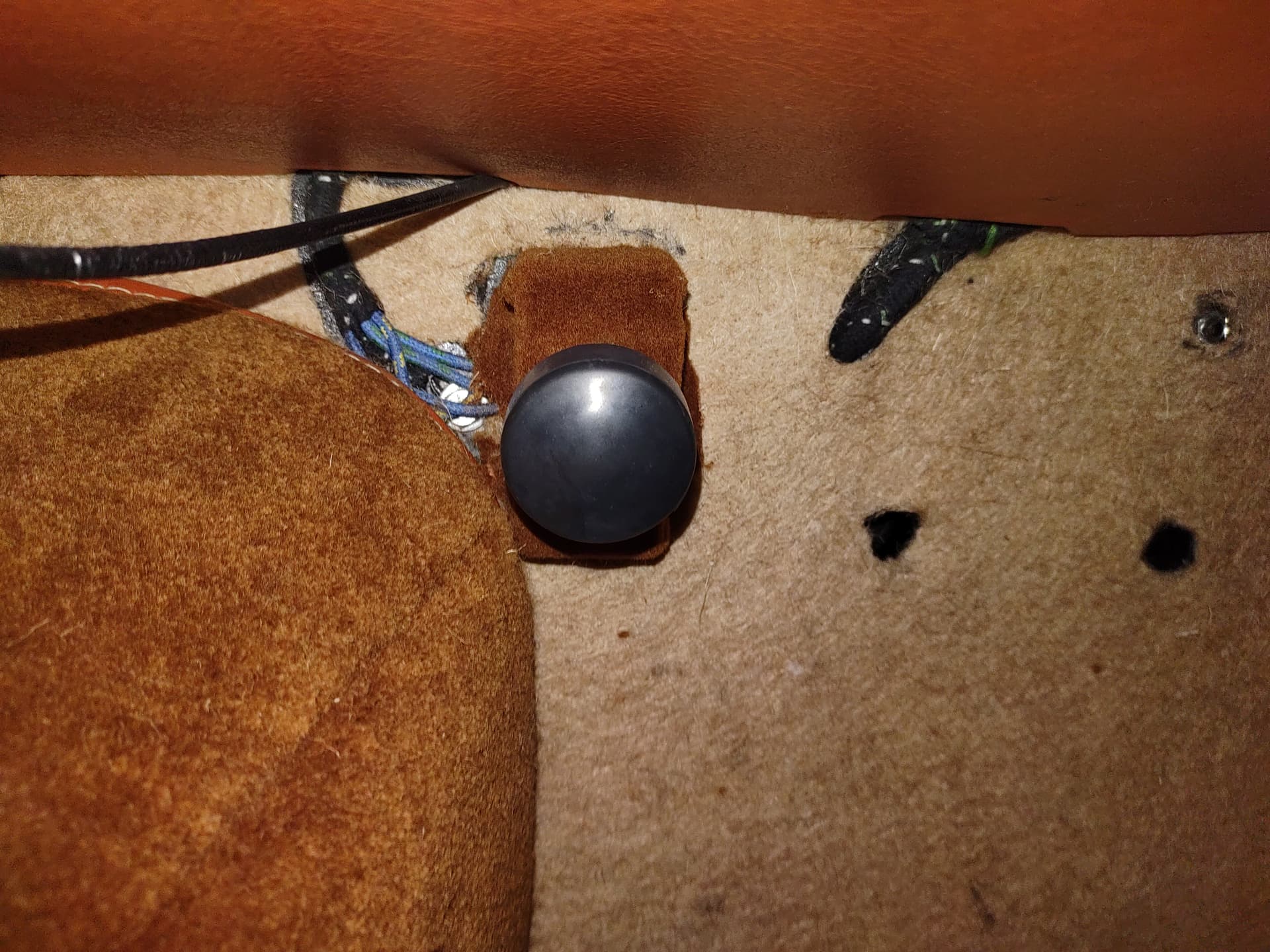
Thankyou Lukas, your photos are very helpful.
Can I request one more please - a shot from inside the cockpit, showing the position of the dip switch pad?
Best regards,
Tony
Hi Tony
You are welcome Sir!
The dip switch bracket shares the two bolts with the solenoid thus the position is easy to determine.
Best Regards
Lukas
Just let me know if you need some more pictures

Wonderful, thanks Lukas.
How convenient that is, no welding, just two bolts.
Best regards,
Tony