Hello, I have a RHD XK140 FHC. A couple of queries: Grateful if anyone could tell me if the front to rear harness section runs through the sill (a la the diagram in Viart’s book) or via the screen pillar/roof channel before emerging at the rear boot compartment? Secondly, what route from o’drive relays to gearbox should the overdrive loom take? Any pics would be very useful. Thanks in advance, Jon.
Hi Jon
Both main front-to-rear loom and overdrive loom enter the sill below RH footwell.
Overdrive and reverse wires exit the sill together at the cross-beam (you should be able to find the hole there) and go 90° along the cross-beam to the gearbox.
Rear lights loom exits the sill at the base of the inner wing, run up along the inner wing and into the boot, down right for RH lights, and across boot upper part to boot light switch and to LH lights.
Fuel pump and fuel sender wires enter chassis below RH footwell.
Fuel pump wire exits chassis further back at fuel pump level.
Fuel sender wires exit chassis high up on chassis rear leg (you should be able to find the hole there), go 90° to the LH side along rear chassis cross-beam (in front of tank), and down along tank left side to the fuel sender.
You need semi-rigid electrical wire to pull the wires all the way from the rear of the chassis and from the rear of the sill.
HTH.
Francis
1 Like
Francis, thank you very much for the very detailed response - all is now very clear! Best regards, Jon.
Bonjour Francis
J’ai un soucis sur ma jauge à essence ; elle a cessé de fonctionner un peu avant que je ne change tout le faisceau électrique. Et depuis, rien de mieux.
Manoeuvrer manuellement le bras du Fuel sender en dehors du réservoir ne provoque rien au tableau de bord : l’aiguille reste fixe. Même chose avec un Fuel Sender neuf.
A ton avis, un mauvais branchement ? Mauvais contact ? Tester le faisceau ?
Merci d’avance
Bonjour Hervé
Si tu as éliminé les causes 1. Du sender, 2. Du faisceau électrique (tester la continuité de chacun des fils entre chaque extrémité avec un ohmmetre), il ne reste plus que l’instrument.
Pour ma part, arrivé là je l’envoie chez mon fournisseur Speedograph Richfield.
J’ai eu le même problème que toi après restauration de la voiture.
J’ai tout vérifié et la jauge restait toujours bloquée sur zéro.
J’ai résisté à envoyer la jauge chez Speedograph et j’ai roulé comme ça.
Je suis même tombé en panne d’essence dans un rallye 
Et puis un jour par hasard j’ai trouvé qu’il suffisait de taper un petit coup sec avec l’index sur le tableau de bord à côté de la jauge pour qu’elle marche.
J’en suis toujours resté là et je donne un petit coup sur le tableau de bord en démarrant.
Je pense qu’il suffirait de démonter la jauge et tout bien vérifier. Peut être qu’un des deux petits aimants a été déplacé… ou quelque chose comme ça.
C’est un partage d’expérience… ou plutôt un partage d’ignorance 
Amicalement
Francis
-------- Message d’origine --------
Sorry Hervé, I did not realize this is not a private discussion !
So, if your fuel gauge still does not work after you have eliminated 1. Sender if you have replaced it, 2. Wiring if you have checked continuity of each wire from end to end with an ohmmeter, it only leaves the gauge as faulty.
At this stage, as far as I am concerned, I would send it to my usual supplier Speedograph Richfield.
I had the same problem as you describe after compete restoration of the car. I checked everything and the gauge remained stuck to zero. I resisted sending it to Speedograph (I was too lazy dismantling the dashboard), and I kept driving. I even ran out of fuel one day during a rallye. 
And then one day I found out that it only needed a little tap on the dashboard to set the gauge working …
I just left it as it was, and I just tap the dashboard every time I start the car …
It probably just requires dismantling the gauge and give it a check. One of the two little magnets may have moved out of place, or someting of the kind.
This is just sharing of experience … or rather sharing of ignorance !
Regards
Francis
If the tank unit (sender) is disconnected the gauge should flick to full when the ignition is turned on. If it doesn’t, there are three possible reasons.
- The supply to the B terminal of the gauge is missing
- The gauge case is not grounded
- The gauge is faulty
Item (3) subdivides as follows:
3a) The pointer is stuck to the endstop. This can happen if the gauge has not been used for a while and is probably the reason why Francis’ tap method works.
3b) The pivot is binding.
3c) One of the coils is open circuit or, more likely, the wire to it is broken. The wire is very fine.
The correct fuel gauge for a 140 is incredibly hard to find so well worth having it repaired professionally or doing it yourself if you have the dexterity to deal with small instruments and can solder.
Eric
Shropshire, UK
Merci beaucoup pour ta réponse
rapide, Francis !
Je vais essayer ce petit coup sur le cadran (décidément après le
coup sur le démarreur ou la pompe à essence, en voilà un autre à
ajouter à la panoplie du parfait jaguariste Amicalement
Hervé
Hervé
Tap (firmly) on the dashboard.
Not on the glass !

Francis
Oops! Thanks for the precision Francis! 
Thanks a lot, Eric!
If knocking the dash does not cure the problem, I will try your path.
I should have precise that my gauge is not stuck to zero nor to full but a little above half volume.
Hello folks, as a follow-up to Francis’s detailed response, does anyone have a photo or can they be specific as to where/how the front to rear loom routes from the main harness to reach the sill below the RH footwell? Once at that point, how/where exactly does it enter the sill? The reason I’m asking is that my vehicle has been repaired in this area and my previous harness was totally shot, so it’s not immediately obvious as to where the original route/entry point should be/actually was! Thanks so much for your ongoing help. Jon.
Jon,
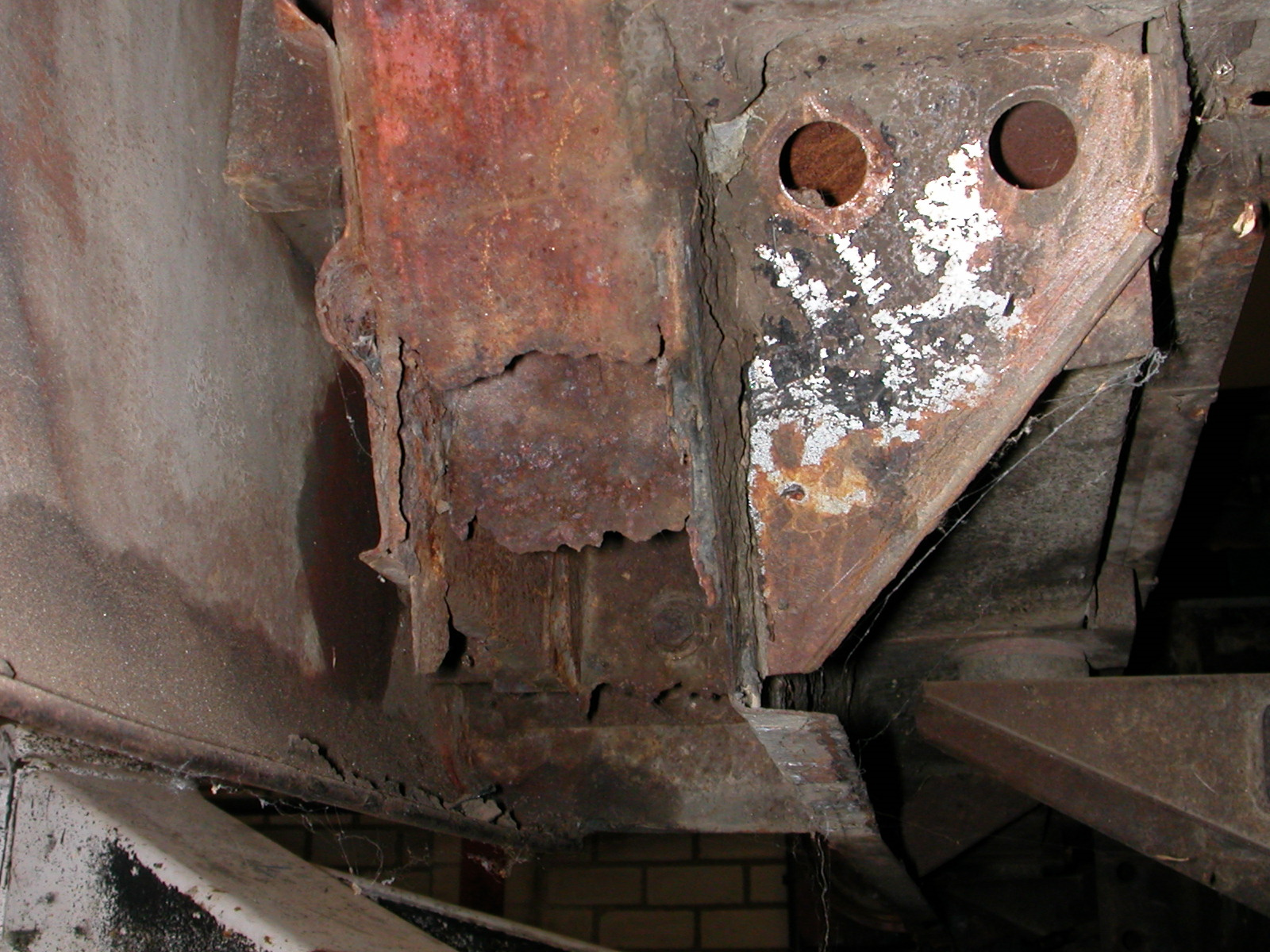
Although a LHD FHC versions, these photos might be of help. The rear loom runs first from the fuse box to a hole (with rubber gland) in the RH inner wing, through the battery box and downwards to arrive at the RH sill. There are two holes at the front of the RH sill (rather high up) and one is for the rear loom. I’ve also added a detailed picture of the holes in the sill before restoration started.
Bob K.


Thank you very much Bob, your info and pics are excellent! Jon.
Hi
There are two P-clips which hold both looms together on the footwell.
One P-clip is high up on the vertical part of the footwell, the second in the middle of the lower (oblique) part of the footwell.
Francis
Thank you Francis! That’s clear now. Jon.