IDK. I doubt it, but if you want to take the time, just make a notepad list of the LB246 18 way HP connector, and LB247 14 way connector functions and wire colors on the 92’ and 94’ and compare them. The illustrations differ, but the actual numbering may be the same.
Garry, I have the XJS instrument panel schematics for the 1989, 1992, 1995-1996 for the V12 and the 4.0 where applicable… My wife’s 1992 has a facelift instrument cluster, and two '94 spares. I can tell you there are some very minor differences - an example would be the Amber ABS light and Red Brake light when the Teves IV came to the XJS. No change to the panel, but how the wires from the panel connected to the T4 ABS - very simple, So, I can say, with respect to the subjects we have discussed - no changes.
FYI, my wife’s first XJS was an '89 coupe - that was the car I did the first crossover from an '89 Panel to the '94 facelift panel - it worked perfectly, and was the basis for my crossover charts.
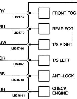
Let me say this, You can completely remove the instrument cluster from the car, and the turn signal system will work just fine, but no panel indication lights. You have told us that your turn signals work fine - except for the indicator lights. To me, that means your connections to the indicator lights are not correct. You are not the first to be confused by the GW to GR an/or the GR to GW connection reversals. I realize most of the wire colors match, but the turn signals are one of the exceptions to that. Fundamentally, the plug, plug pin position, and function are primary over the wire colors - so let me give it another shot with regard to the turn signal indicator lights only:
LHTS - The wire (GW) from the '89 big plug A6, must be connected to Facelift big plug A3 wire (GR).
RHTS - The wire (GR) from the '89 small plug B6, must be connected to Facelift small plug B10 wire (GW).
'89 big plug “A” has 18 connection positions Facelift big plug “A” has 18 connection positions
'89 small plug “B” has 12 connection positions Facelift small plug “B” has 14 connection positions
Connected as above, the indicator lights should work correctly - other wise suspect burnt out bulbs or instrument panel damaged wiring.
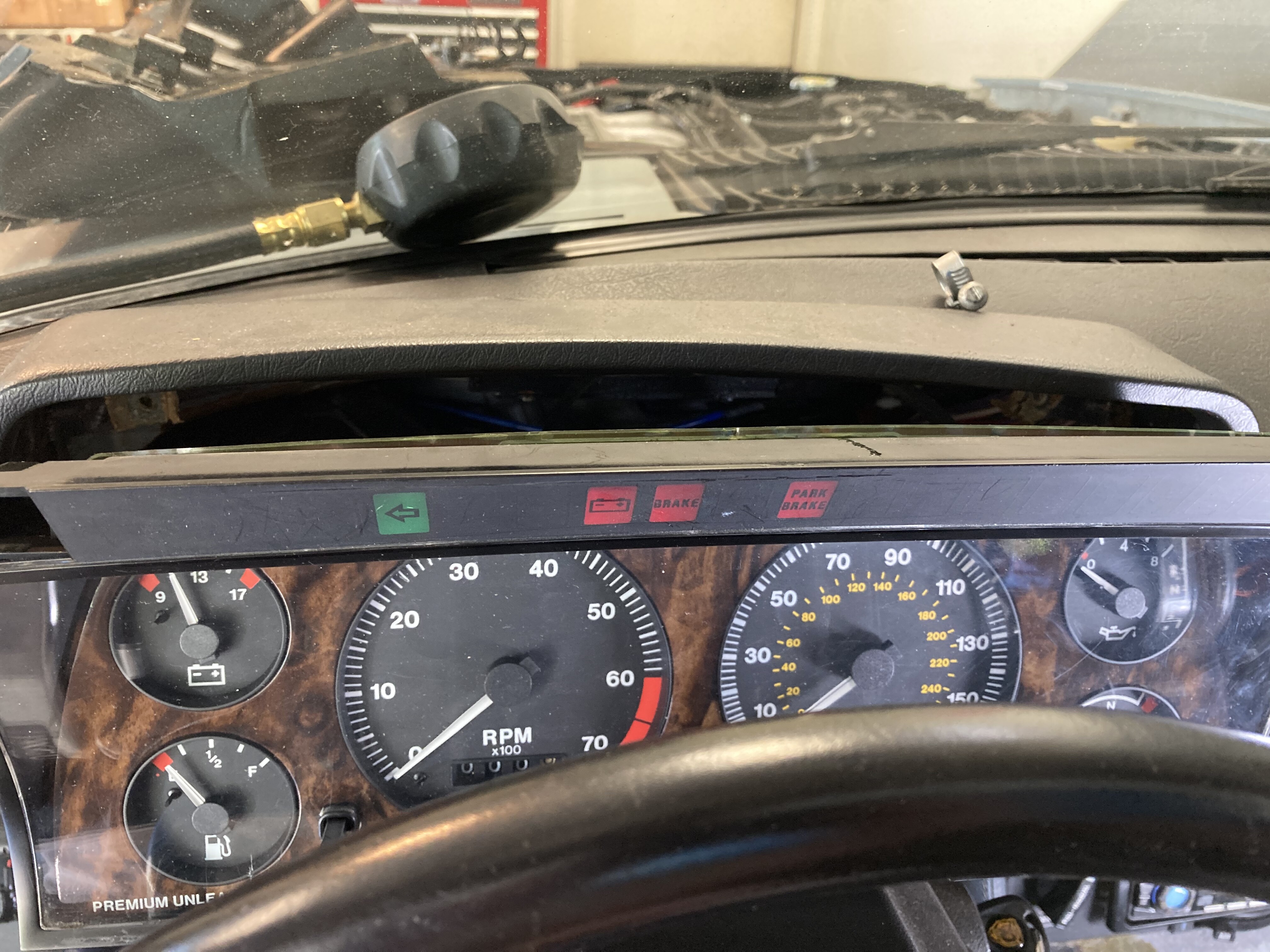
Was looking at cluster, and noticed that the parking brake was not lighting up… Checked all connections and now when I pull up brake lever, gas guage and batt.guage die… I’m wondering if I didn’t buy a bad unit from Ebay seller… Also now odometer has quit… Something just isn’t right… Me
Garry ,
Working on it - here is some more stuff to look at while I am correcting the cross over chart. And you can also let me know of any suggestions you might have, or errors you might see.
Thanks,
AE
Scott, FaceLift TS & Hazard Schematic.pdf (221.3 KB) XJS Panel Swap Source Data.pdf (2.0 MB)
Open to suggestions, questions, corrections and ideas
Then, on to putting it together.
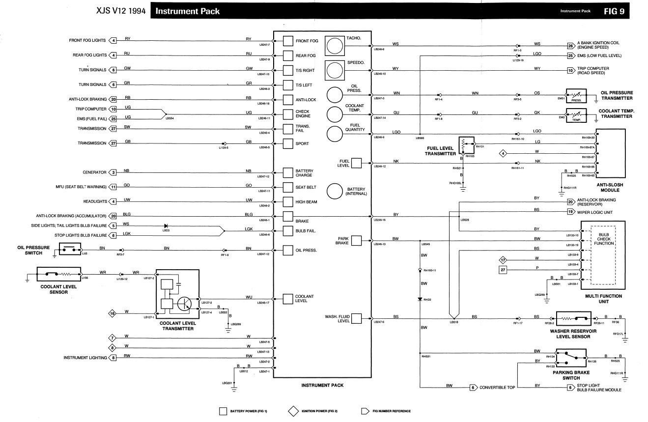
In case you didn’t have it, included is the Facelift schematic so that you can see where I was going with your idea of bypassing the diodes - FL TSignal & Hazard Warning system has no diodes.
AE
Attached are the source documents and comparisons of pre-facelift instrument panel connections
Hey Gary: got my blinkers working on my facelift cluster. I had to bypass the 2 diodes going to each light on the cluster. The diodes are in a terrible spot behind where the steering column attaches to the body behind the cluster. I found I would get voltage to one side of the diode (used a safety pin to punch into the wire) when the turn signal was on. Looks like the original pre-facelift cluster would blink when it got a ground with the 12V coming from the blinker relay port C (I assume the cluster would blink opposite of the outside lights). The facelift cluster works with current flowing the opposite of pre-facelift, so it has no diodes and no wire from port C on the blinker relay and should blink at the same time as the outside lights.
So by jumping past the diode makes the Facelift blinker lights work as it is wired like the Facelift car.
Tangent on this topic, the relay for the blinkers on our cars is VERY quiet. With my new smaller steering wheel, I cannot see the blinker arrows. If I have my stereo on, I cannot hear the blinkers. So sometimes I am that old man with his right turn signal still on
Is there a simple way to put in another relay that ticks much louder? I always liked the Ford signals, they ticked very loud, you knew it was on.
Kirbert
(Author of the Book, former owner of an '83 XJ-S H.E.)
29
All 4 are used on pre-facelift, 3 are used on post facelift
The 4th spot on pre-facelift flasher is port C which is for the cluster. If you convert to a facelift cluster you don’t need the 4th one.
The other three are 12V, ground, and the flashed 12V for the outside bulbs.
Kirbert
(Author of the Book, former owner of an '83 XJ-S H.E.)
33
Too many cars require specialized flasher relays. My current Mazda Protegé5 uses two different ones depending on which options you get. The relay includes the bulb failure function.
Personally, I’d go with the buzzer idea. That way you’re not replacing the flasher unit. Just wire it up to buzz when the blinkers blink. Might need a diode or something to prevent it buzzing constantly when the parking lights are on.
I have a 1988 XJS with a TH400 but have converted to a 5 speed and am trying to get the speedo to work with the rear end of a 1994. The 5 speed Tremec does not support the DAC4569 impulse sender. I can make the speedo spin when I twist the small paddle at the end of the DAC4569 with it wired up in my hand. Now I am trying to use the pulse signal from the differential. Unfortunately I missed the cut off In 1988, the pulse generator DAC4569 on the transmission was eliminated. The speedo interface and diff mounted speedo transducer began with VIN 144263, about half way thru the '88 model year.
I can see the diff signal in the trunk across the red and blue wires looking at resistance an voltage changes with wheel spinning by hand. I have been sending the output from the trunk to where the DAC4569 was connected.
I have a used speed interface that should send a signal to the speedo connections but the speedo does not move.
Any help would be great.
Thanks
Chris
Chris,
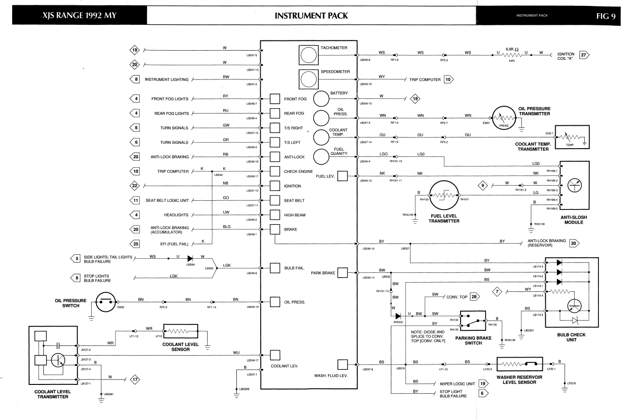
It would seem to me that you are going in the right direction. You apparently have a signal from the transducer on the differential. I don’t believe the speedometer in the instrument panel changed between sometime in 1988 and the late pre-facelift cars… But then I don’t have a schematic for the speedometer. The only difference would be the use of the speed interface when the diff. mounted sensor was used. My guess would be that you have an open circuit or short somewhere in the circuit, or reversed polarity somewhere, or a fault in the speed interface. You did not mention the shielding over the blue and white wires - see attached speedo circuit from '89 XJS. After you have checked all those things and still don’t have movement of the speedo, I would suggest you contact a company named “Dakota Digital” - Google it. They make digital converters for speedometer and tachometers as do several other vendors. A phone call to them to explain your problem would probably be best. On the other hand, I think there are folks on the this forum that have done this, (use rhe search tool - magnifying glass at upper right hand corner - and perhaps on “jaguar Forums” X27
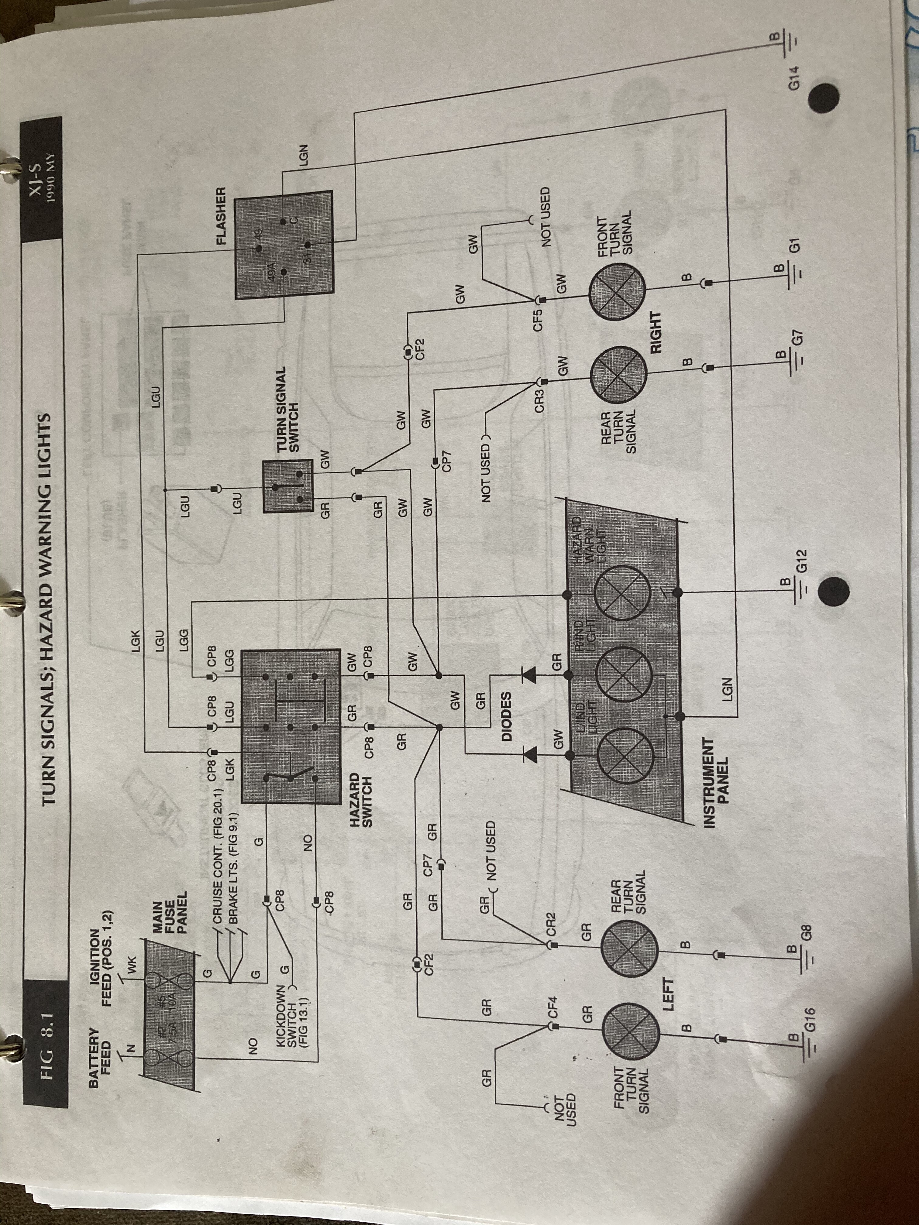
Hi all, I’d also like to better understand the pre-facelift indicator warning lights in the dash. From the circuit diagram, both are fed from the flasher/relay (pin C), yet when you move the indicator stalk to indicate right, the left dash lamp is fed from flasher/relay pin 49A (via a diode).
I think this means that when the right indicator lamps (external) are being turned on and off via 49A, that the left turn dash lamp is also being provided 12V (on and off at the same time)… or at least the diode is. So… why? Is this because both dash lamp indicators share a common on/off/on signal from flasher unit C-pin, and therefore applying 12V to both sides of the left turn dash lamp (while indicating for a right turn) is a net 0, therefore the lamp stays extinguished? I guess then the diodes prevent current at the dash lamps (via the C-pin) racing out to the actual external indicator bulbs.
Now the bit I don’t really understand is where these lamps get a ground from? Does the turn signal switch (indicator stalk) connect 49A to the “turning” side and make a ground to the “non-turning” side? This would make sense, as for a right turn this would then provide a ground to the right indicator dash lamp.
Perhaps my indicator stalk then might explain why my lights function perfectly with the exception of the left and right indicator dash lamps (hazards, hazard warning lamp, external indicators all work fine).