Air Intake Aperture aka Bonnet Opening: I need profile advice - Final Update Added

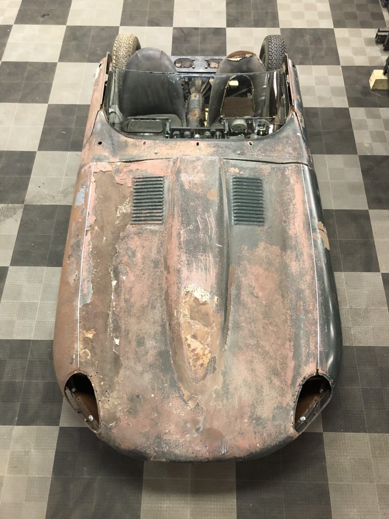
Some people, when they wake up in the middle of the night, lay awake thinking about work or personal problems. I think about my Etype restoration! Sad but true. So I hired a panel beater to help me with my bonnet center section. It is by far the roughest item bodywork wise on my 63 FHC. He is semi-retired and has a wealth of experience but never on an Etype. BTW he is also going to help me spray my Opalescent paint. I have “rough assembled” the lower nose section, center section, and two wings on the car. Things look generally pretty good. But the bonnet center section has taken some licks and was previously repaired with an eye on limiting repair costs. I removed the plastic filler. He went to work smoothing out the peaks and valleys. We identified some holes that need to be welded. He wanted to know what the profile for the bonnet opening should be. Good question? I did some research but appreciate input from the forum.

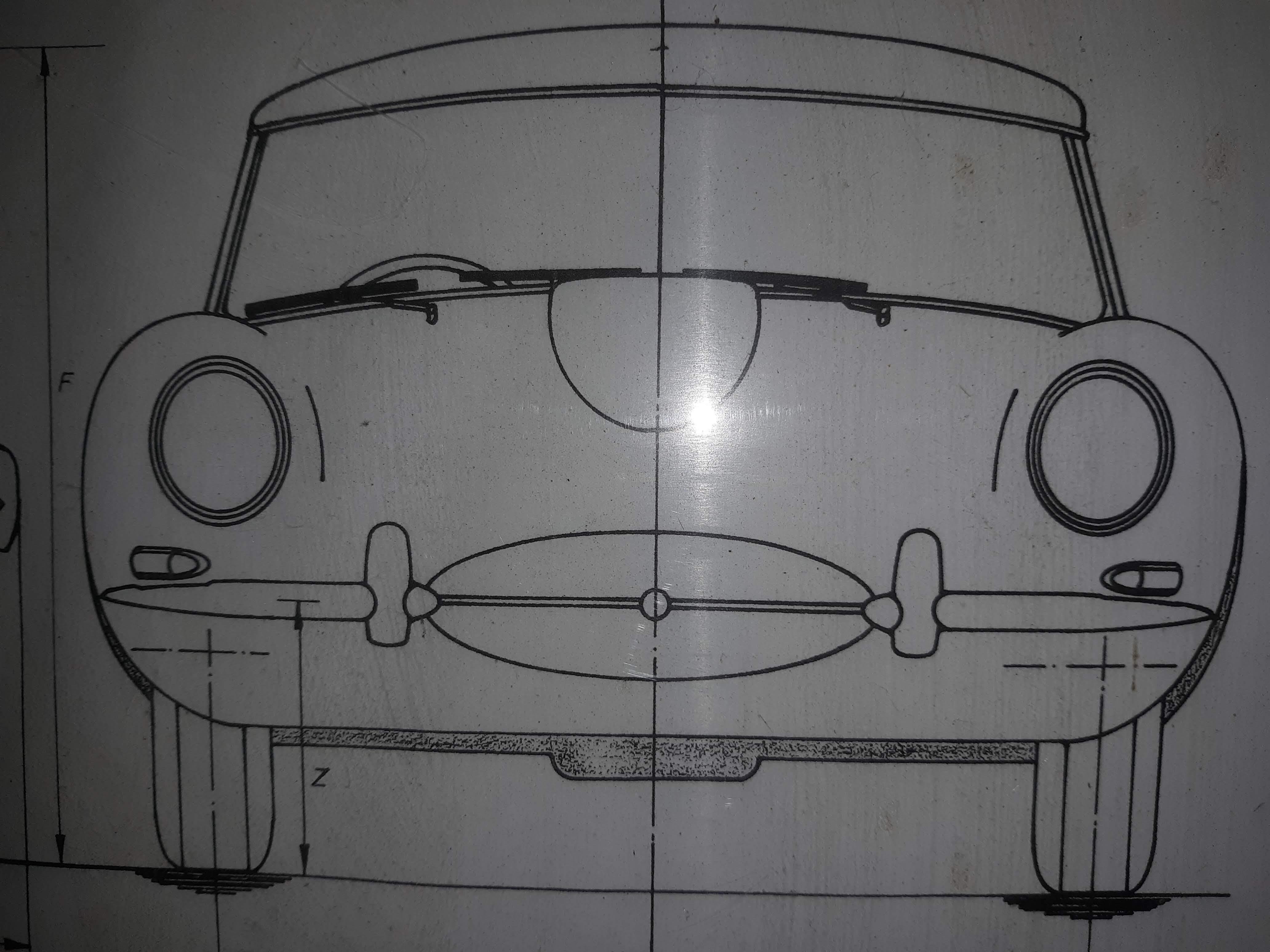
I have one of those large poster size drawings with early Etype OTS dimensions.


In general, it would appear that the opening is symetrical about a horizontal centerline.

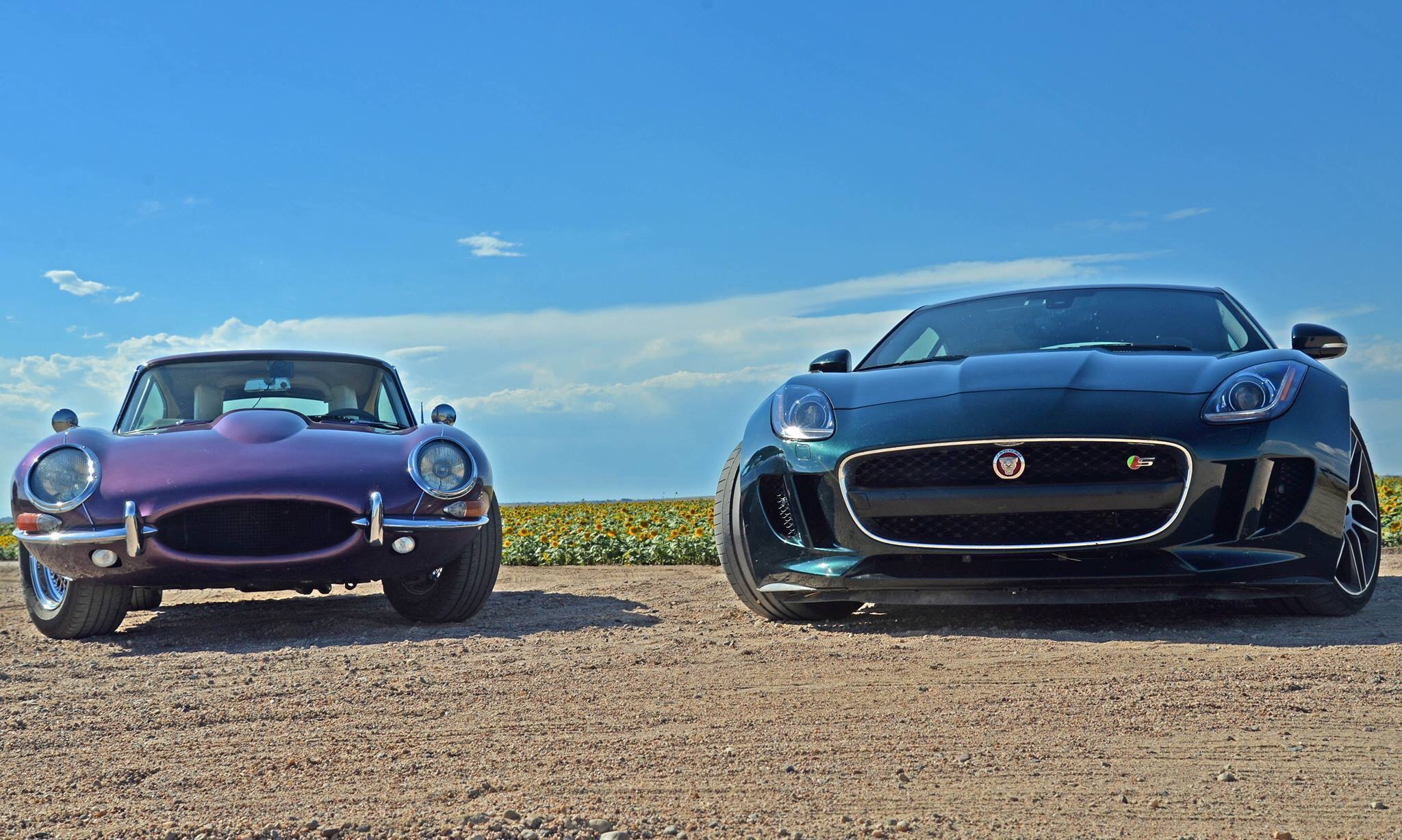
I looked at a bunch of photos on XKEData. Things can be confusing based on camera effects but I have convinced myself that generally the opening is symetric about the motif bar.
G1

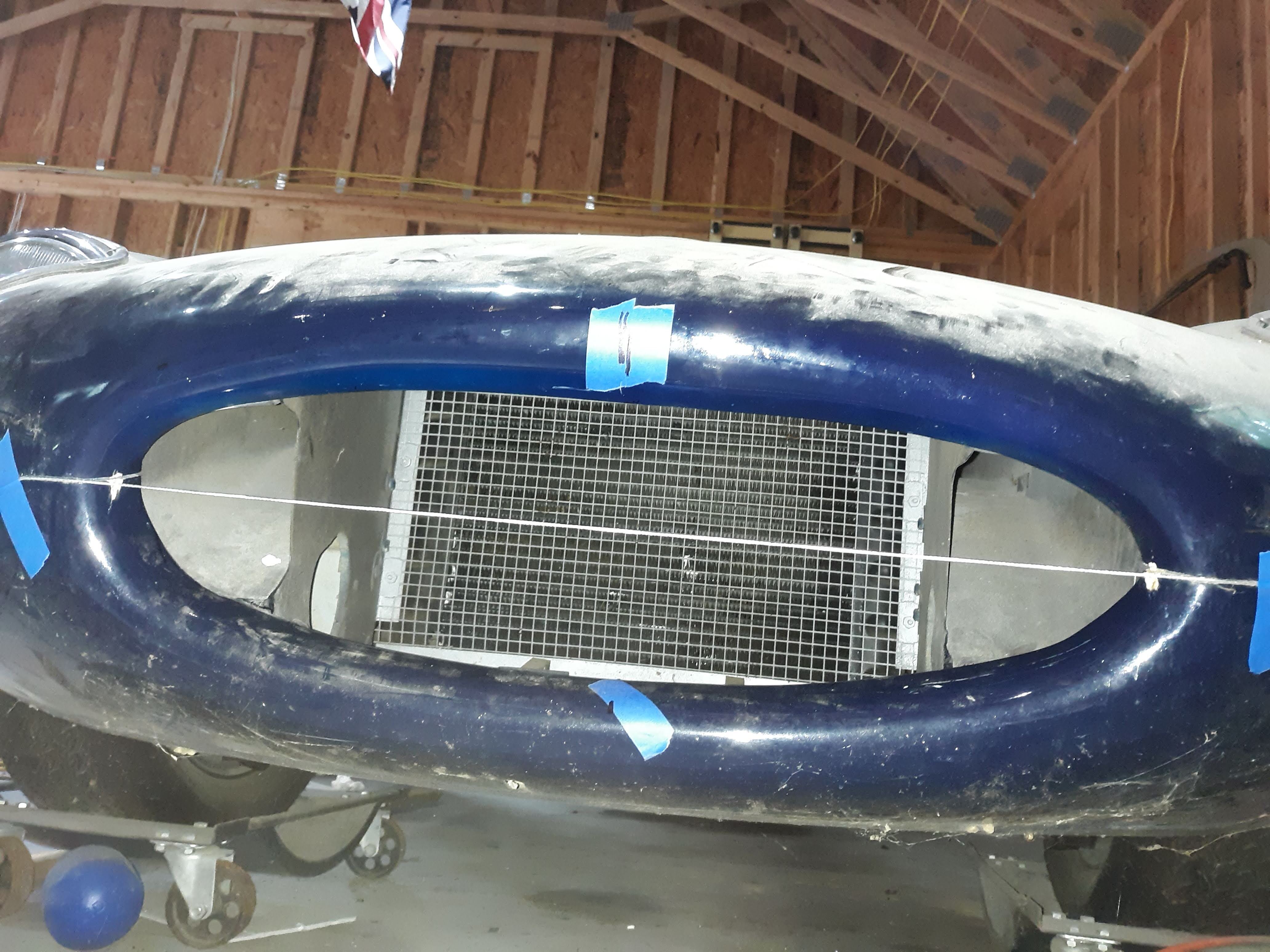
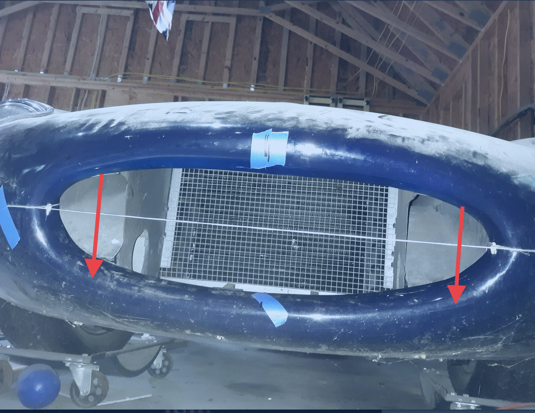
I happen to have a 1966 build 2+2 in the shop. It has an openheadlight bonnet which may not be original to the car. That said, I took off the bumper and pulled a string across the opening, embedding the ends in the body seam between the lower nose and the bonnet. It sure looks symetrical to me. BTW the horizontal dimension on this opening is about 24 1/2", which agrees pretty closely with the 63. My forum searches lead me to believe the opening did not get bigger until the Series 2.

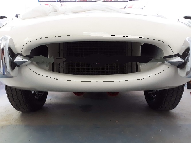
And then there’s my bonnet. Not symetrical :frowning:

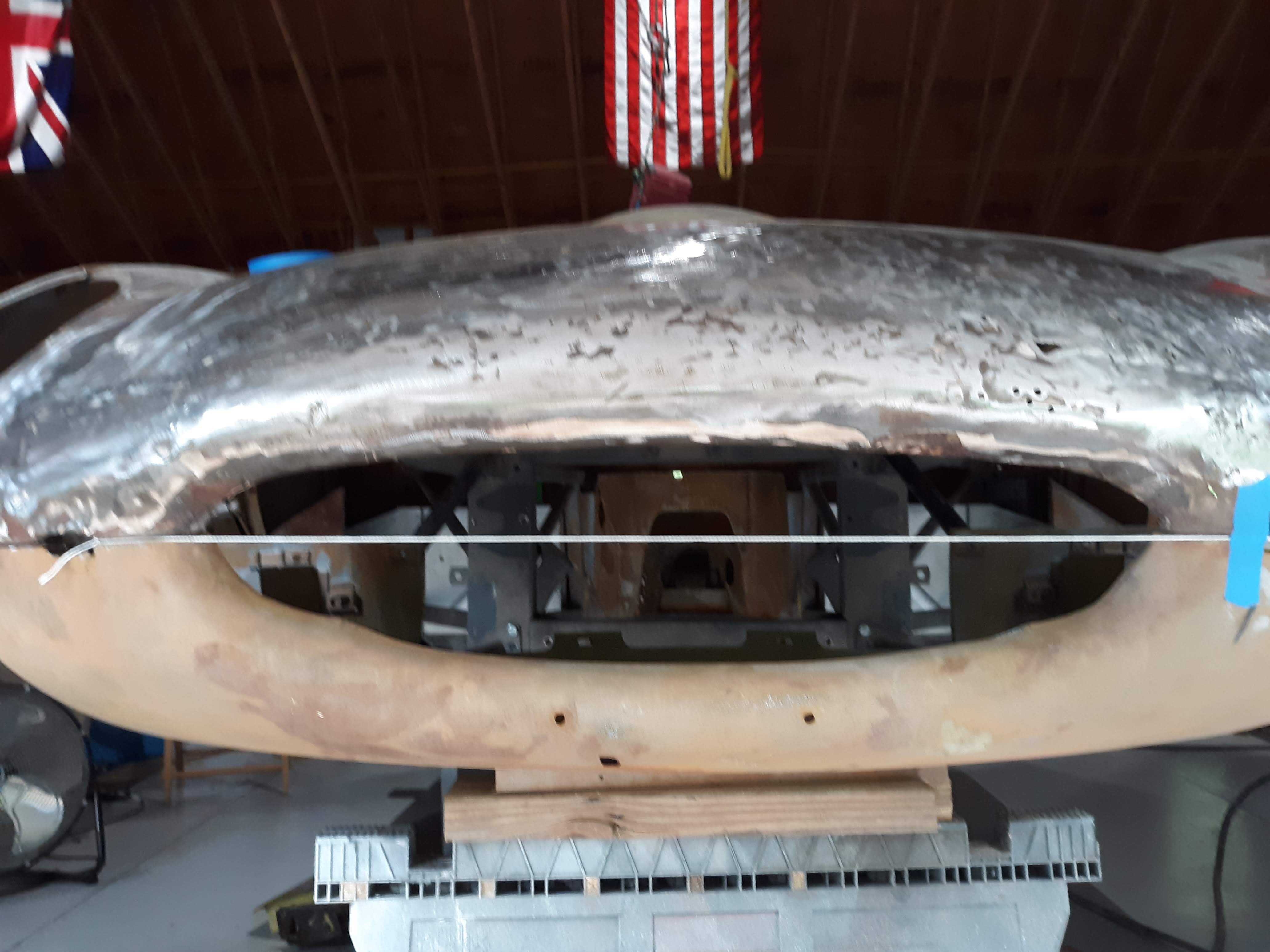
Measurements are compounded by the fact that the bonnet opening is “tilted” forward at the top but if you try and establish level planes that touch the opening edge on the bottom and the top, it would appear that my bonnet opening needs to come up by about 3/4". I think he can get there but I don’t want to send him on a wild goose chase or impossible mission. Purchasing a new bonnet center section from SNG is an option, but not without it’s own potential issues. Plus I’d reallly like to save this one if I can.

Also there is the Plan View profile, which is a view that appears to never be the subject of photos on XKEdata. Here is what the Jaguar drawing shows.

It almost looks flat in the middle. If I hold a straight edge on my 67 it doesn’t really have a flat section but a gentle curve. The 63 is pretty flat across the middle. The panel beater suggests that it could be due to collision damage.

The big question: Was it the design intent for the opening to be symetric?

I think the answer is yes. If so, I can take a profile of the lower section opening and “flip it” about the centerline as a target for enlarging the upper opening. It’s going to be tricky.

Does the Plan View of a undamaged bonnet exhibit a little bit of curvature?

If yes, we will probably achieve some of that as we roll out the lip to make it sit taller.

Is it safe to use my open headlight bonnet as a template?
Again, I don’t really know if there are any telltales that differentiate a bonnet with the larger opening. My 67 bonnet opening is 24 1/2" across and about 7 1/4" as the crow flies from the edge of the lower lip (at the middle) to the edge of the upper lip. If I can make templates off this bonnet, it will vastly simplify things. This bonnet shows zero signs of collision damage.

Sorry about the long post but if you’ve read this far, that’s a good sign for me. I searched the forums for keywords like Templates. I came across a bizarre thread (some of you may remember) from a guy who requested templates and immediately got really angry and insultive with everyone. I promise not to be “that guy”. Thank you thank you in advance!

1 Like

My recollection is that S1½ openings were larger than S1 and smaller than S2. I probably have a photo that shows that, will look.

Early bonnets were symmetrical but as the moulds wore they became less so. Early original car:
Screenshot-20200718-033009

Later on (replacement bonnet from 1970’s):
Screenshot-20200718-032935

Also the earlier bonnets had a very pronounced crisp crease around the bulge which became softer over the years:


Harvey, for what it is worth, the Coventry Foundation has the original blueprints for the bonnet from Jaguar. There is also a lot of other neat items useful when needing information for a proper restoration.

Looking at your photo, it looks like they may not be symmetrical. Drawing a vertical line at a right angle to your string. Notice how the top “triangle” is a different shape than the bottom? It appears the radius at each end is different, with the top having more of an arc. This might be a function of the photo, but I don’t think so.

The picture isn’t shot from dead center so it’s hard to say, but there does appear to be a difference between the right and left sides.

So next time I get knocked down by an e-type I’ll be sure to take a look because thats just about the only orientation a human body needs to be at to see the “flaw”.

Bob, I went out and took a look and I would agree, the top has more of an arc. Of the 3 cars I have in the shop, that opening just looks a little bigger than the rest. Again, I do not know the exact provenance of either of my 2+2 bonnets, since according to the car numbers, they should have both come with closed headlights, but they have open headlight bonnets. But I am now thinking that the blue car would not be my best bet as far as making a template. Speaking of blue, the dark cars fool your eye. When I researched XKEData I began to only look at light colored cars, as the dark ones were difficult to see the details.
So I moved on to my white 2+2. It also came with an open headlight bonnet, converted to closed headlights with the M-M kit. The interesting thing about this shot is that I bought a replacement lower pan, from Welsh. I just called them and they said the lower pan I bought was shown to fit everything from 61 to 67. But it is a replacement pan, not an original one. That car presents yet another “look”.

Since it has a new lower pan, I took a template of the lower half of the opening and then compared it to the pan for my 63. Of course they don’t match! The 63 is more rounded in the corners. So it should come as no great surprise that shapes morphed over the years, without an overt change in part number or mention by Haddock. But I do agree with David that the openings changed over the years.

Les, you are right. Most of the photos are taken from a normal height and a lot of this doesn’t really show.

The following picture was taken at my first HPDE, 10 years ago. I proudly put it up at the office. The office wags said the Corvette looked like a shark chasing a guppy! I was crestfallen. But I had to admit they were right.

1 Like

Dick, your suggestion about the Coventry Foundation is a good one, especially if they are in Columbia, less than 4 hours from me. Do you have some contact info?

Just when I said no one takes pictures of the nose from above, I found this one of a 63 OTS, at Monocouque Metalworks. Chuck even conveniently included grid lines on the floor, although a little skewed!

And another of the bonnet opening.

Chuck at Monocouque metalworks is a great resource. He’ll gladly talk to you about this problem. A lot of bonnets have been hit. They typically get pushed down and in because they run into the back of a taller car or truck. It would not surprise me if your bonnet was pushed down by an accident. I know mine was. Another giveaway is how the tubes fit inside the center section.

Was that at a NASA event?

It was an event sponsored by Tar Heel Sports Car Club at VIR.

I have talked to Chuck about bringing the bonnet to him for repair. Unfortunately, with the tremendous success of his business, he is booked way way out. A good problem to have. I have been looking at his website for tips and ideas, which is where I ran across the pictures.

I agree the center section has been pushed down. Based on my measurements today, it needs to go back up about 3/4". I’m not sure my panel beater and I are up for that on such a convoluted shape. But I’m still looking and learning.

Make a LARGE sandbag, get a couple of plastic panel hammers…learn away!

It amazes me how many hugely expensive restorations seem to ignore this issue altogether. When I was looking for a car 18-24 months ago I came across several supposedly $150K-$250K cars (not that I planned to spend that much) where the air intake was far from symmetric about a horizontal axis. In some the bottom “lip” was too flat compared with the top, while in others the reverse was true. It just seems such an obvious defect that I don’t understand why a restorer will spend so much on paint etc but not get the shape right first. Front AMCO bars will hide the defect, which may be why so many cars have them…(duck for cover :grinning:
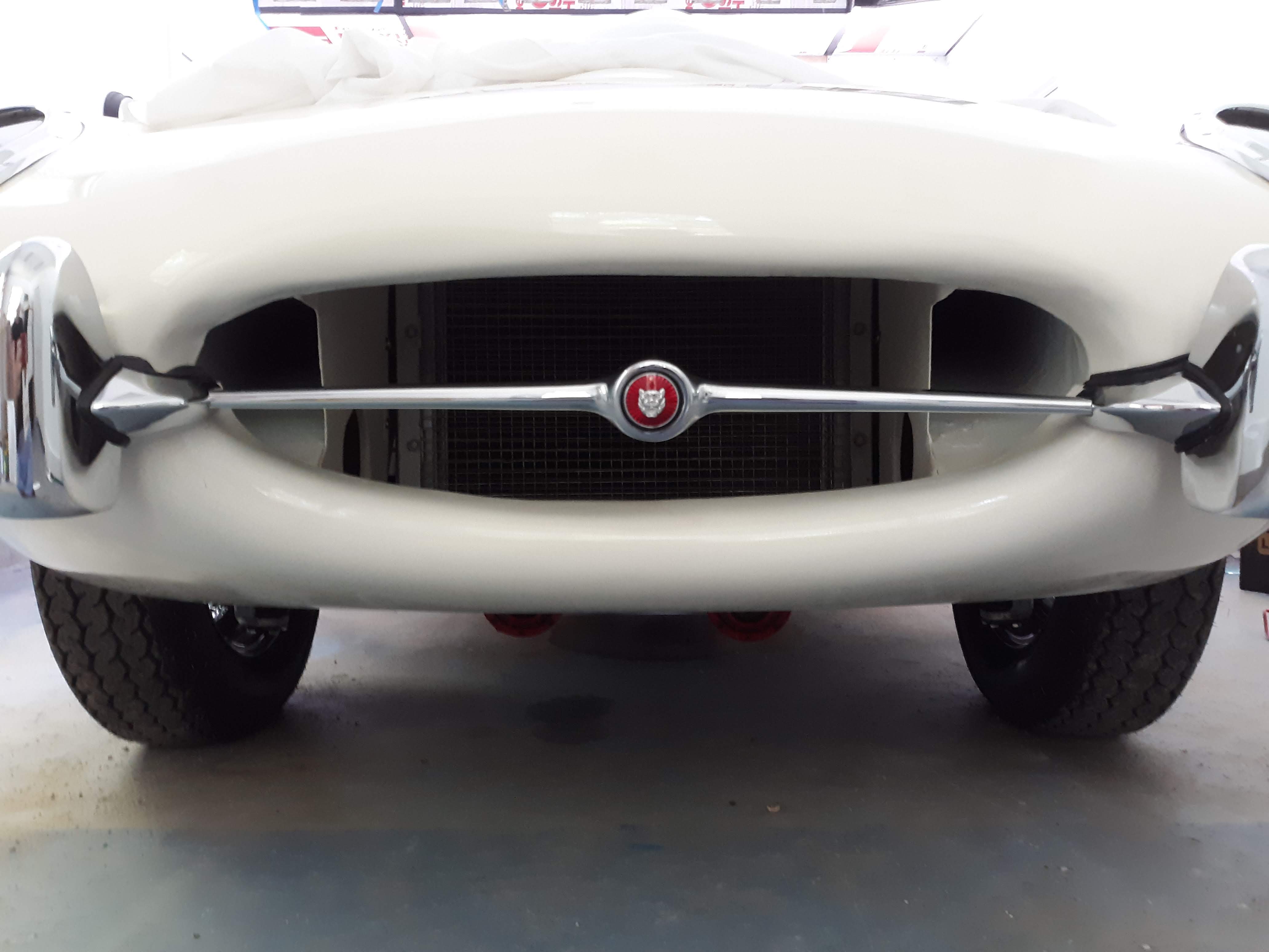
). The cars with a flat top lip tend to have that lip protruding further forward than is correct too, which accentuates the problem. I suspect that they were subject to accidents where the front of the bonnet was crushed. The white car here seems to have that problem.
mouthgrid
I have no clue how you would go about fixing this though… Good luck.
-David

1 Like

Hard to see, but Tweety’s aperture was undamaged/unmolested.

1963_Jaguar_E_Type_Purple_Harry_W_001

Another view…

2 Likes

So Harvey, I answered you in an email, but here are the dimensions of my aperture. some conditions, the center section is a replacement, but undamaged. The bottom half is from some unknown Jag and has a slightly wavy mouth. that said, the left right of just the replacement is 24-7/8" and the bottom half seems to agree. The top/bottom measures 6-7/8" but the bottom of the aperture is a bit wavy, so it may be 6-3/4".
Here is a suggestion, you bottom half (not getting personal here) appears to be “right”. Make a profile of its opening and flip it over to see how that lines up with the top half that my eye says is squished. Maybe that will help? It also seems quite sure that even the factory made adjustments for every car they built.
Interesting observation on the sharp edged line around the power bulge.

Scot, I have done just what you recommended. When I flip it up, it appears that we need to move that profile up about 3/4". I’ve got to huddle with my panel beater. That sounds like quite a bit for such an intrinsically stiff cross section.

Stretching and planishing WILL get you there. Not easily, and LOTS of multiple mockups, but doable.

Tim the Tin Man taught me that!