My '87 XJ6 hasn’t had very accurate fuel gauge readings for a while. I also had problems getting readings when switching tanks–would have to switch back and forth a couple times to get it to finally read. More recently not getting any reading on L tank. R tank works but maybe not well?
Took the tank change-over switch out and cleaned the contacts. Switches nicely now but still no reading on L tank.
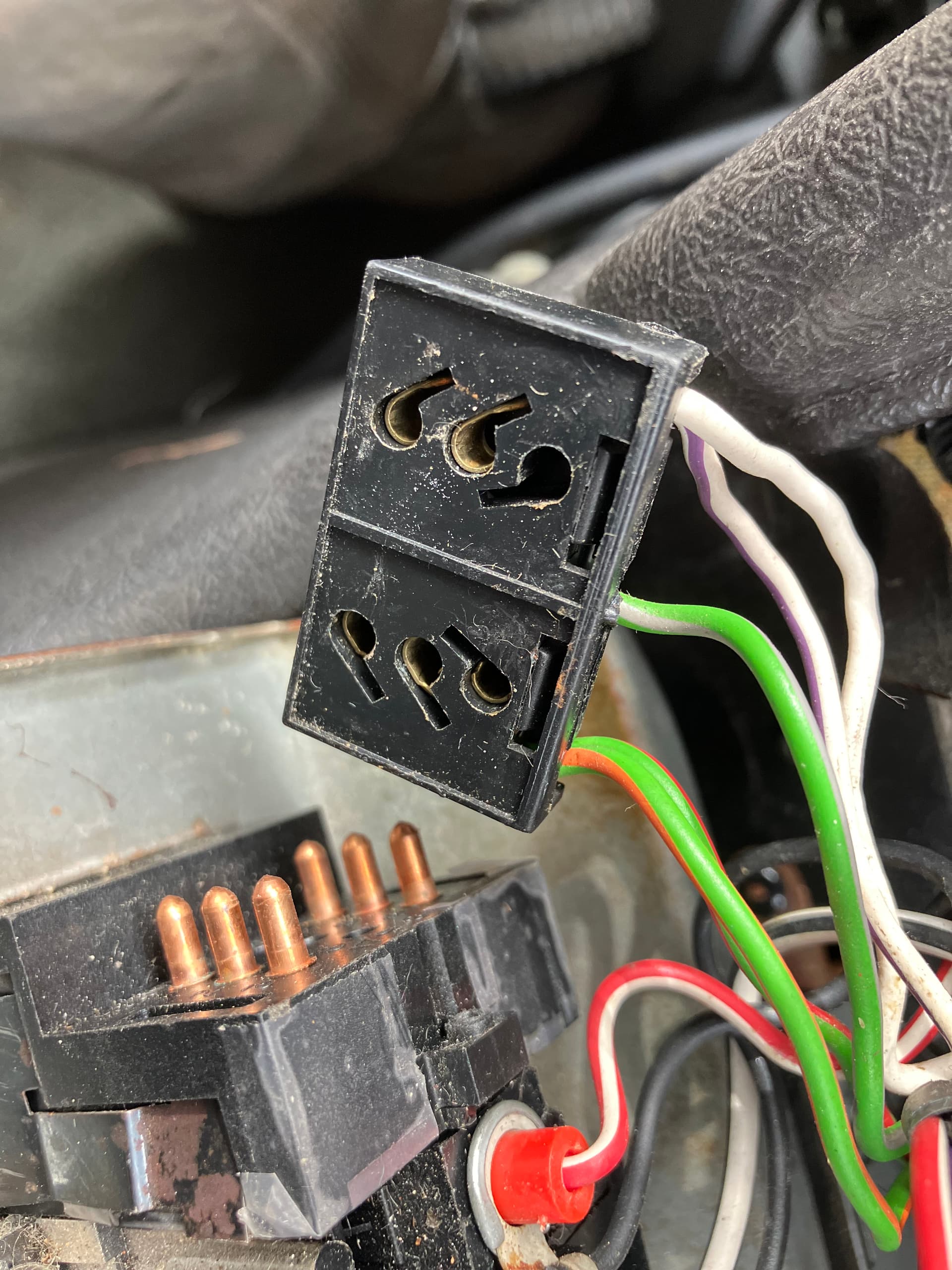
Found no voltage on green/orange wire at tank sender. Then found 5.5v on green/orange (supply I presume) contact on pull-off portion on back side of switch (see pic). Then found no voltage (???) on green/orange pin of multi-pin connector under dash as shown. (Which makes no sense to me, if I do get voltage further downstream. Cleaned pins several times.
As I read the schematic, power first goes to the fuel gauge, then the tank switch, and finally the tank sender. I’m left thinking that I’m not getting 12v OUT of the fuel gauge. Does that sound right/can that happen?
And if so, what’s the best way to get the gauge out?
If by “power” you mean 12 volt “+” then the only place you’ll find it is on the solid green wire at the back of gauge itself.
The other wires (from the senders, thru the switch, and from there to the gauge) are a variable ground…with the variability coming from the resistors on the sending units. This varying ground is an input to the gauge, not an output from the gauge.
Anyhow, easy test…
With the key “on” ground the wire at the sending unit. The gauge should go to “Full”. If it does then you know the gauge is OK, the wiring to the gauge is OK, and the power supply (solid green wire) to the gauge is OK. The only thing left is the sending unit.
Try this on both sides.
If the gauge doesn’t operate when grounding the sending unit wires then you have some a bit of digging ahead to find out why. Dead gauge, most likely…but there are other possibilities for sure.
Ah…there’s my confusion. Didn’t really know there was such a thing as varying ground. Don’t see that the wiring schematic indicates it either?
First thing I tried was grounding the wire at the sending unit–nothing. I know the gauge works because the other tank does register. So…?
My first assumption had been that the problem is in the change-over switch. Still suspicious but not sure how to test it, now! Grounding the N/O wire at the gauge side of that switch should show full tank, yes? Then would need to ground the tank side of the switch, N/O and N/K wires, at the switch, to prove the switch is ok?
From the gauge; one path to the changeover switch - then two identical paths to the tank units. So your ‘first assumption’, based on test results , are well taken…
The switch has two functions; tank selection and fuel gauge display function. The white wire takes power, through the inertia switch, to the changeover switch - which, with ‘right’ selected, (switch ‘out’) powers the changover and fuel return valves - white/purple wire. With ‘left’ selected (switch 'in there is no power from the switch to these valves…
The second function; the gauge is connected to the changeover switch by light green/orange wire. From the switch; light green/slate to the ‘left’ tank unit and light green/red to the ‘right’ tank unit - at the tank units both wires are changed to light/green.
All faults revealed by Doug’s testing regime. To test the changeover switch itself; you need to disconnect relevant ‘out’ wire from the switch itself and measure voltage at the respective switch connections - it should read 12V with appropriate switch selection. No voltage means the switch has not switched…
Additionally; with the tank unit wire disconnected; measure resistance (ohm), from the switch end, to ground - it should read the appropriate resistance for the amount of fuel in the tank. However, with a possibly malfunctioning tank unit any ohm reading between ‘0’ and ‘1’ indicates that the wire connection is intact…
Consolation; doing the testing requires less time than reading the above…
You know, instead of “getting smarter everyday” ( a great website, BTW) I sometimes think I’m regressing. With all the above help I think it will work now (L tank so low on fuel it barely registers). Problem was a bad switch.
When I first took the switch apart, the contacts looked pretty good. Cleaned them all anyway, and put it back together. Didn’t work. Took it apart, cleaned again–this time used DeOxit–and it still didn’t work. Bent one of the arms on the U shaped pieces of copper and it does work now, but I’m still not sure exactly what the problem was. Fully expect it to quit working, soon!
Am still confused about one thing: Frank, are you and Doug saying the opposite here, or am I not understanding?
“To test the changeover switch itself; you need to disconnect relevant ‘out’ wire from the switch itself and measure voltage at the respective switch connections - it should read 12V with appropriate switch selection.”
and
“If by “power” you mean 12 volt “+” then the only place you’ll find it is on the solid green wire at the back of gauge itself.”
That, to me, is a confusing and confudling term as “ground” is “ground”. You either have a “good ground” or you don’t. And when you don’t have a good ground, you have a problem.
At least that is what so many posts here say about so many problems.
In the case of gouges, you have a “good” +12V, a “good” ground (0V reference point relative to the negative terminal on the battery as measured with a meter), and a variable resistance between the two.
“Ground” isn’t variable. The resistance device is the variable. Be that a fuel tank sending unit, oil pressure sending unit, water temperature sending unit, etc. They vary the resistance ‘to’ ground.
When you dim the instrument cluster lights are you “varying ground”, or are you varying the resistance to ground?
Ground is ground and if it isn’t ground, the you have a bad ground someplace.
The switch connects power, ‘on/off’, Thon - and ideally a test lamp must be used to check for ‘power.’
Voltage is more elusive; you may have heaps of ‘voltage’ but the ‘power’, involving current flow, may be missing due to bad contact, high resistance. Which doesn’t affect voltage - as long as there is not a complete break in the connection. The ‘voltage’ is the difference between a connected connection and ground - ‘power’ is the amount of current that flows through a connection…
But any resistance in a circuit affects ‘voltage’ when the current is flowing. Ie, on a disconnected connection no current is flowing, and has ‘voltage’ - either ‘12V’, in our case (or more precisely; battery voltage) or ‘0’. When we measure voltage at a point; we measure the point’s voltage compared to ground - if we want to measure ‘power’ we need to measure the current flow…
In normal conversation we omit the finer points, and tend to assume that both parties do the same - but with the same interpretations. Which is not always the case - but I understand, or think I do, what Doug says…
Ie, the ‘in’ wire to a resistance (instruments, motors or whatever) has ‘unlimited’ ‘power’, current capacity (limited by wire resistance and/or power source capacity) - in the ‘out’ wire; ‘power’ is limited by the resistance in the item.
Certainly, Jerry - but ground is the end of a connection; every connections winds up to ‘ground’. Which, as you say must be perfect - or the circuit won’t work as intended.
In the case of the fuel gauge; the gauge itself is grounded through a variable resistor - we still say the gauge is grounded in this way. To be formally correct, we should say; the gauge’s ground wire (which is actually formally incorrect, but commonly accepted) is connected to the tank unit. Which is, in turn. connected to ground, which of course must be good.
The same applies to all connections, however complicated - if the ultimate ground is bad, the circuit doesn’t work correctly. So a ‘bad ground’ is not inappropriate usage - it expresses that the ground connection has a resistance that should not be there - as you say…
And that too. Do you see the common connection in both of those.
And which is different from this:
If we were to accept the term “varying ground”, they we need ti change “switch” to “intermittent power” … but we don’t.
We have ‘power’ (+12V, which actually is “varying”, depending on the condition of the battery and charging system, so let’s just use use ‘power’ … and ‘ground’ (which is just metal chassis connected to Bat-, so let’s just use 'ground’l.
Ground does not vary.
As you pointed out, the “connection” ‘to ground’ (and, conversely, the connection ‘to power’) goes through a device (switch, resistance, variable resistance, or a fixed permanent connection such as a screw, etc) and it is that device which is what makes things work as they do.
I am simply pointing out that “ground” does not “vary”. It is the connection ‘through a device’ that is connected ‘to ground’ that varies.
To get back to the ‘real’ world , and say all this in a different way, I SHOULD be able to measure 12v at the green/pink terminal on the tank sender, using a ground other than the sender ground (to ignore its variable resistance). Yes?
And, I SHOULD be able to measure 12v at the green/orange terminal (the wire from the gauge) at the switch . Yes? (I was measuring at the wire end, with the wire disconnected from the switch.)
Test light didn’t work at either of those locations, and voltage at the switch was 5.5v, with tank connections not hooked up.
That second test doesn’t seem to indicate a switch problem but fixing the switch fixed the problem, so I think I’m still confused???
Thanks.
Thon
Tank unit wire colour is light green in my wiring diagram, Thon…?
12V; only with wire disconnected - if current is flowing, voltages reflets resistances ‘upstream’.
Yes
It’s a bit complicated; the gauge likely acts as a ‘voltage splitter’ - using 5,5V to the units for safety and better precision. In which case a 12V test lamp will not light - adding that high resistance within the gauge may restrict current…ditto…
That’s because car electrics is confusing - and
auto electricians highly valued. But since things are working; it’s the results that ultimately counts…
One pair of contacts energizes / de-energizes all three solenoids (on - off) and the other set switches the input between the two tanks for the fuel gauge.
So:
White is 12V
White/purple should have 12V when switch is depressed (Left tank)
Light Green/Red should connect to Light Green/Orange when switched to Right tank
Light Green/Slate should connect to Light Green/Orange when switched to Left tank
A “bad” ground is not “ground”, it is a "bad connection TO " ground … but “ground” is still there.
No, the fuel gauge sending unit is a varying resistance that connects TO ground. “Ground” itself does not vary.
I guess you missed the part where, if we were to accept “varying ground” as a term, then we would no longer have switches … we would have “intermittent power” as power would vary.
Except that power (12V nominal) does not vary. The connection TO power (via a switch) varies. Power is still 12V nominal.
In that same way, ground (chassis connected to -Bat terminal) does not vary. The connection TO ground (via a variable resistor) varies. Ground is still at -Bat terminal as 0V reference for power 12V nominal.
And in the course of their work they probably don’t get too bogged-down in semantics, preferring instead to get to work and fix the car
Fortunately for all of us these cars are fairly simple in terms of electrics and common faults (and fixes) already documented. A great many problems are solved by simply cleaning connections and contacts, this following simple visual inspection and without even the knowledge to use a 12v test light.