Creating a new thread for this topic that came up on another thread.
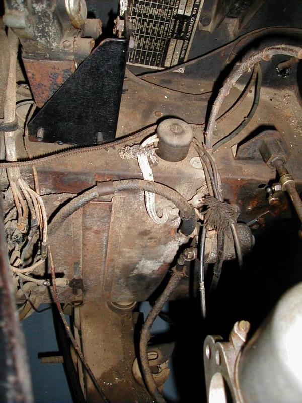
This junction box is found between the wiper motor and throttle shaft pivot only on 120s from late '51 to early '52,
and after 20 years we are gradually approaching the point where we can say we have some understanding of it.
My 679187 has one but no wires to it because the car was rewired by a PO.
679042 has one, suggesting the lower limiting chassis number is lower than that given in the SPC.
679265 has one.
and thanks to Simon we can see that it has 3 wires and is clipped to some manifold nuts. That is new information.
679359 does not have one, suggesting the upper limiting chassis number may be correct.
On our last discussion of this we concluded that the wiring powered the coil, oil level sender and starting carb, and that this wiring change was related to moving the coil from below the front carb to above it.
However, I thought there were only two wires to the junction box.
So I will be very interested to know about the third wire, what it does.
And yes, this little detail comes under the heading of “running changes made at the factory while keeping up with hectic production schedules” and is probably not covered by the major wiring harness makers of today.
Hey, hey! If we can believe the SPC (fatal assumption) yours (Feb '52) is the second to last car to have it. Looks like 2 wires coming from the instrument panel. What can you tell us about the wires going to the engine?
Also interesting that your car seems to have body color on the scuttle.
Mine is Nov '51 but didn’t leave the factory until Feb '52.
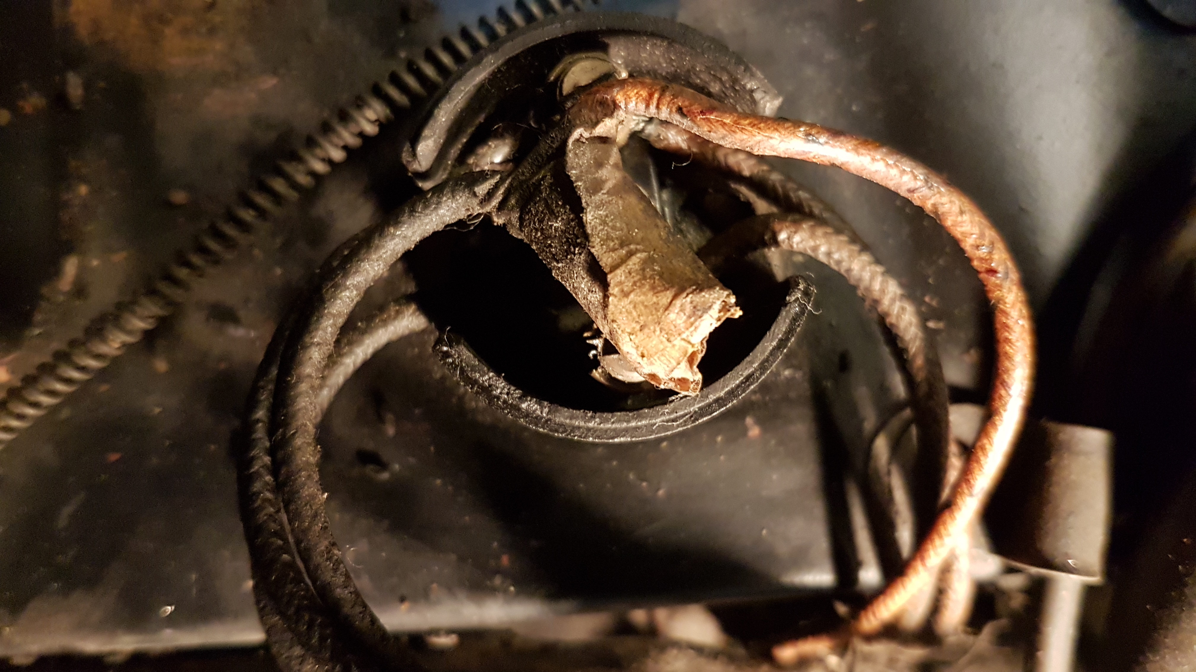
Here are two photos showing the Bakerlite junction box in more detail.
Three leads come off the main harness but bizarrely the box only contains two terminals.
The third lead doesn’t go into one of the two terminals but is twist joined in the box.
Exiting the box, two leads go to the carburetter solenoid and the third to the coil C8.
In other words the coil got its own dedicated lead from the harness without having to go via the carburetter solenoid (as in the Viart wiring diagram)
.
However looking carefully behind the battery cable where the third (twist joined) lead comes from, it doesn’t look like it came through the firewall in the sleeve with the other two. Possibly it was either initially wired separately to the other two or for some reason someone decided to rewire just this lead at a later date.
I will have more on this when I rewire behind the firewall (not soon).
Yeah, that twist join doesn’t look like factory work, at least nothing that I would approve if I was manager there.
Two terminals is correct.
I would have thought two of the engine wires would be together into one of the two terminals.
One to carb solenoid and the other to coil SW (switch), certainly not CB (contact breakers).
The two wires that go towards the engine had been cut when I acquired the car (see photo) hence I don’t know how they were routed. It had previously been partially dismantled so not necessarily a good example of originality.
It does appear to have had original paint on the scuttle. the car was originally black, although it was a combination of rust and primer when I got it. The bulkhead paint is actually black although it looks more like a metallic blue in the photos.
Ok, black under the bonnet is correct for all cars up to late '52, even black cars.
Interesting that you have the Lockheed tag on the brake fluid reservoir, as does Simon and myself. Some don’t. Probably deserves a separate thread if we want to do a survey of that feature.
679265
I have retraced the “third wire” back to the dashboard where it is connected to an on/off switch (see photo) . It appears to be a manual operation of the carb solenoid.
I havn’t worked out yet why I can’t find any reference to this dash layout, which is at variance to all the other photos, drawings etc of dashboards, however my theory is that although it is an original push button dashboard switch which certainly looks very authentic,
it has spade connections. Thus I think a previous owner added this as an incorrect way of fixing a starting solenoid problem. It does confirm that there were only two leads though box C 5258 originally. Any further thoughts anyone?
Your dash looks very similar to mine, 679187.
Also interesting that you have two extra undocumented knobs either side of the map drawer or radio, like mine has, although not the same knobs. Mine operate two parking lights behind the quarter windows, which were required for France, where mine was originally.
Your reference sources may only show the later more common dash layout.
There were early and late dashboards for the FHC, chrome knobs vs Bakelite knobs for one thing.
I would like to see more pictures of your metal tray for the map drawer. That is another item for which I had a lot of trouble finding information.
I see your map drawer cutout has rounded corners, where mine has square cut, yet another early variation in map drawers.
The round bakelite terminal blocks have been used on Jaguars from late 1935 [ 6 terminals , 3 wires in 3 out.]on the steering box for manette wiring
They are a proprietary item used on many English cars , Some are only 2 terminals and are a smaller diameter.
Repros are available but don’t have Lucas moulded in
Prior to these bakelite lids with a single screw they had a snap on metal lid and these are worth a small fortune. My Jag service place uses a similar snap on lid for the complimentary peppermints that are left in the car after a service. sadly,slightly smaller diameter.
Rob,
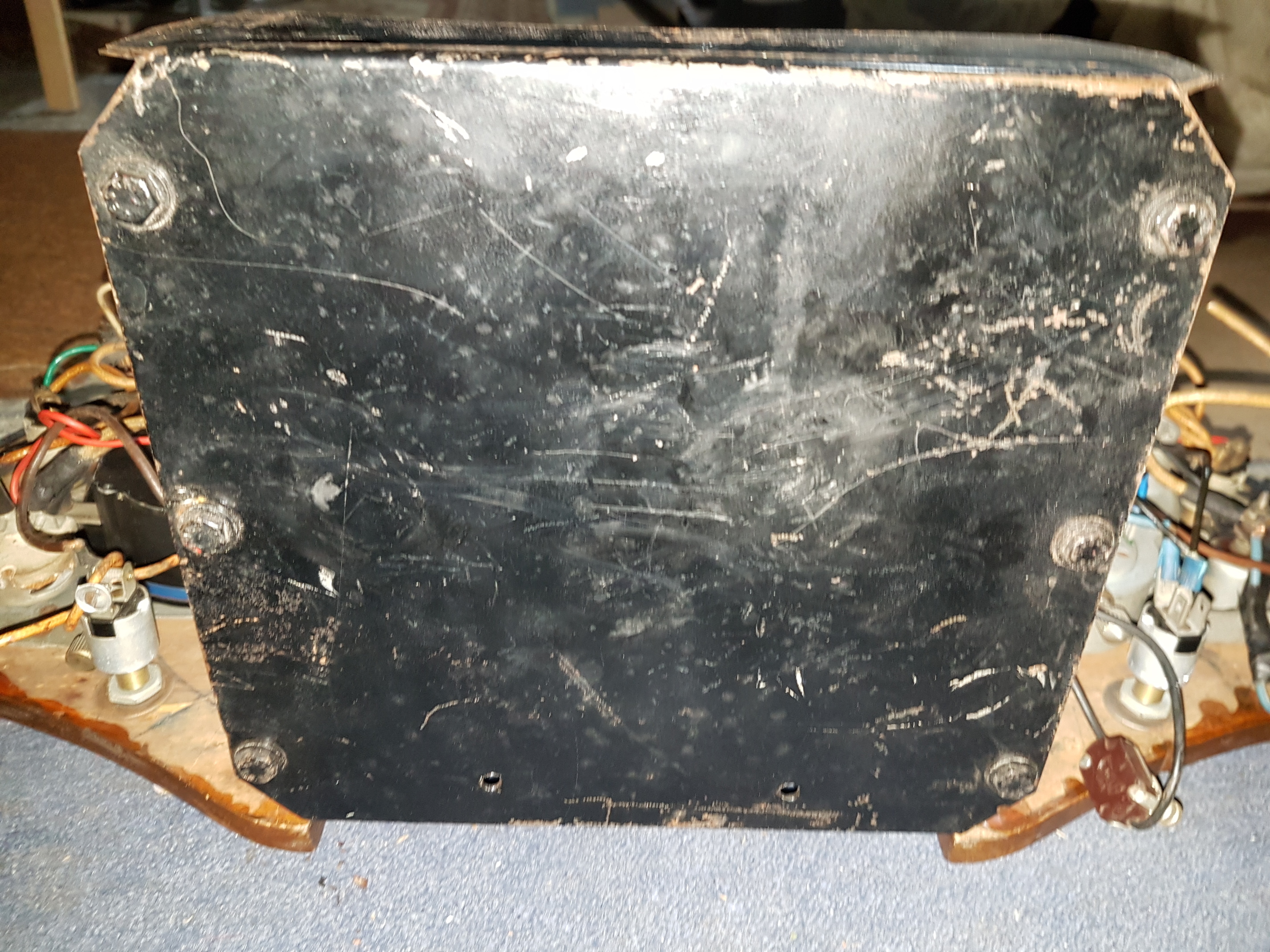
You did ask about the central fascia drawer some time ago but I only exposed it this week.
Here are some photos. Let me know if you want more detail.
BTW, are there any rules about the size of images posted on the Forum or is the sky the limit?
If images of the drawer frame aren’t anywhere else in the Forum or Archives then may I humbly suggest they are put in their own category somewhere, as nobody interested will find them here!
Many thanks for those map drawer support pix. They confirm that what I made from scratch based on the support found in another forum member’s car was correct. http://www.jag-lovers.org/snaps/snap_view.php3?id=1283606872
The standard map drawer and brass support rails found in most 120 FHCs and all DHCs was not right for mine or yours, and for the longest time I couldn’t figure out why, searched for 20 years for that information.
BTW the horizontal marks in the paint along the inside were made by the “bullet” catches and confirm that you had a map drawer at one time. I don’t recall if you said you had a drawer or a radio.
It would certainly be interesting to see a radio mounted in this tray, because mine may have had one.
We used to have a feature on this web site called Photo Albums, where we could post important information like this. It was certainly a valuable tool for this kind of use, though perhaps it may have also seen some abuse and misuse. There was a file size limit at that time, but now I believe files are reduced automatically for the forum.
Yes, it is the standard two post Lucas model. Whether yours should have one may depend on your chassis number.
Look for two screw holes in the place shown in the above photos, between the wiper motor and the throttle spindle.
Distilling the information from all the threads on this forum that I can find, attached is a circuit diagram (with apologies to B Viart as it is hand drawn) showing where we are at present with our understanding. C5258 junction box circuit.pdf (201.9 KB)
Excellent! I have ordered a wiring harness from Rhode Island and will be rewiring my car in a few months when the weather gets warmer, so I will be using this information.