I have installed the entire system in a 1969 e-type FHC that had a/c originally. All the relays (3) are original & working. I have the Bentley workshop manual & the green Ken Ball manuals. The wire color codes do not agree in all cases. The previous owner, one of my best friends, is the only person who has worked on the car. We’re ending a 25 yr. total rebuild.
The man charging the a/c does not like the way the classic auto power source works. I located the original black & yellow feed wire W/in line fuse in the fuse panel.
It receives power from the C1 pole on the a/c relay behind the LF wheel when the key turns on. C2 goes to the alternator. W1(cloth coated looks like tan but seriously faded) & W2 thin black (rubber coated only) & C1(black/yellow) all go into a rubber grommet behind the voltage regulator &,I assume into the fuse box area. There is also a black ground wire that attaches to the relay mounting nut.
The black /yellow wire can feed the compressor & evaporator fan. I would like to tap into the existing a/c electrical system to turn on the fans when the a/c is activated. The 2 original relays are on the picture frame. The otter switch system works & turns on the fans just before temp reaches 70 in the center of the gauge.
I stupidly discarded the original evaporator, but the schematic in both books show that the relay feeds the original a/c switch control that activates the fans through the a/c override fan relay. Even if I had this switch, I don’t think it would help me by looking at it.
Again, I would Like to tap into this system to activate the fans when the Classic air
switch is turned on. I’m thinking the 2 wires (W1 & W2) traveling through the grommet are connected to fuses somewhere & maybe this will work?
I have pictures of the 3 relays & wires if I can upload them(I’m lousy W/I-pad technology).
Question # 2: the red & black wire from the otter switch (that goes to the main fan relay on the picture frame) activates the fans when it is pulled off the switch and is grounded. Do I need to activate the fans W/a ground wire? As my next move will be to take a hot lead off the compressor switch into a cube relay & send to the fans, but
I don’t know if this wire should be a ground also.
Thanks,
Michael Caro
I am replying to myself in an attempt to forward pics
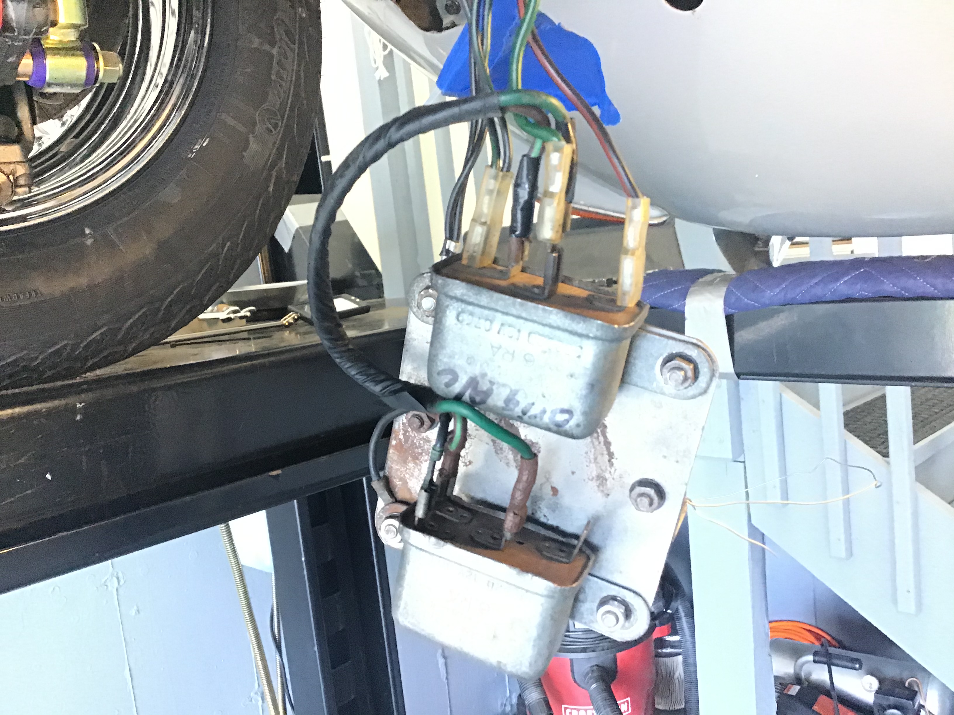

Yeah. 1st photo is the 2 front Relays. They’re upside down in the picture.
2nd relay is the a/c relay behind the wheel well.
Ok. This is going to lead to half a dozen confusing posts, so I’ll take it slow.
The two relays on the picture frame control the fans, as follows:
The “primary” relay is the three pole relay. C2 connects to the fan power source in the fuse box When the relay closes, C1 is powered and supples 12V+ to the fans. One end of the winding on this relay is internally joined to C2. The other end is W1, and is connected to the Otter switch, which controls ground. So the otter grounds the winding, which closes the contacts, which sends power to the fans, which are locally grounded.
To confuse matters, your three pole relay has been replaced with a four pole relay, and I’m not sure how it’s been wired, so we’ll need a few more posts and a closer look at the wiring to figure that out. But I think that you’ll find that C2 and W2 have been jumpered.
Next, how does the AC turn on the fan? The second relay, which is a four pole relay is set up so that C1 and C2 is in parallel with the other relay. In other words, whenever either relay is energized, the fan will be powered. Which only leaves the question of how to set up W1 and W2. W1 is normally grounded, and it looks like that’s been accomplished by a wire to the mounting plate, so you need to make sure that the plate is properly grounded and not hanging in mid air. And finally, finally, W2 gets powered off the A/C switch whenever the A/C is on. This is accomplished by a white white wire that runs out through the cowl near the VR, and runs along the left side frame rail and across.
I’ll let you digest this and come back with Q’s.
Thanks, Michael.
I recognize your logo as last week I bought a set of your Cool Cat fans & installed
them 3 days ago as my a/c guy previously questioned the output of the original fans. Love them. Nice work.
I thought that this a/c system had not been adulterated. So, when I ordered new relays from S.N.G. & I received a C17338, 3 pole relay for the upper crossmember relay I was confused. Also, on the new relay is a sticker: “important, + VE feed to terminal C2”. I do not know what this means.
For the bottom relay they sent an SRB 111. Stymied by the 3 Post relay, I decided
to use what I have in the car, as the a/c always worked as it should in relation to the fans coming on.
I will send additional pics W/the wires & placements. However, if I can go back to original upper relay using the new 3 pole - C1, C2, & W1 terminals that would be my preference.
I will also compare the SRB 111 W/ what is in my car as I believe it has 1 additional
pin but only 4 posts.
Thank you for your time & expertise.
P.S. which fuse # is the fan power source in the fuse box, as nothing is labeled A/C.
I’m guessing after 4 days of trying to assimilate the schematics, It’s fuse # 6?
Michael
This is what I was explaining: C2 is internally connected to the winding, which is a unique configuration for British wiring systems. Since this is a common terminal, that’s where the 12V+ power feed connects. Power usually comes from fuse 6, but sometimes owners will move the fan to an always-on circuit so that the fan runs on after the engine stops (it’s eventually turned off by the otter switch).
Here’s an annotated schematic that concentrates just on the relays. Notice that the C2 contacts on both relays are tied together by the green wire, while the C1’s are tied by the black/green wire. This parallel wiring allows either relay to turn the fan on:

I can help with this small part of the issue. The relay SNG provided is one where the C2 and W2 are connected together inside the can, and only C2 appears outside as a terminal. If all 4 (W1, W2, C1, C2) terminals are presented outside the can, it really doesn’t matter if you transpose the C1 and C2 wires, so some of us get lazy and don’t check However, in the case of the relay in question, if you put the wire intended for C2 on the C1 terminal and vice versa, it won’t work, as now the internal W2 is not getting the power it needs. Hence the sticker on the relay. Hope this helps.
O.K. Michael, Here’s what I have. I will also post better pictures at the end, but if they’re not clear enough I’m going to list the wire paths here.
Upper relay: C1: brown & green jumper wire to bottom relay C1.
33252D C2: green wire to C2 bottom relay.
W2: ground to plate.
W1: not used.
Lower relay. C2: green from harness.
33232D W1: red & black from otter
C1,C2, W1 C1: 2, black & green fan leads,
plus green & brown jumper from above relay.
This C1 pole has 2 pins.
Q# 1: Could this have been done at the factory? As I mentioned this came W/factory a/c. All wires & connectors seem like Jaguar‘s. Surely you’ve heard: “If that fits, it was probably made on Wednesday afternoon”. Also, I now realize this is a 3 pole relay on the bottom & a
4 pole on the top. Possibly built on a Monday?
Q# 2 : If I leave these relays & wires as is & I drew a wire from either the a/c unit or the compressor to the bottom relay W1, will the system & fans work when the a/c is turned on? Somehow, originally they did.
Q#3 : Do you strongly suggest that I take these apart & use the new
3 pole, C17338 on top & the SRB111 on the bottom. And would I
still attach the ground wires to the plate or some other ground
pin?
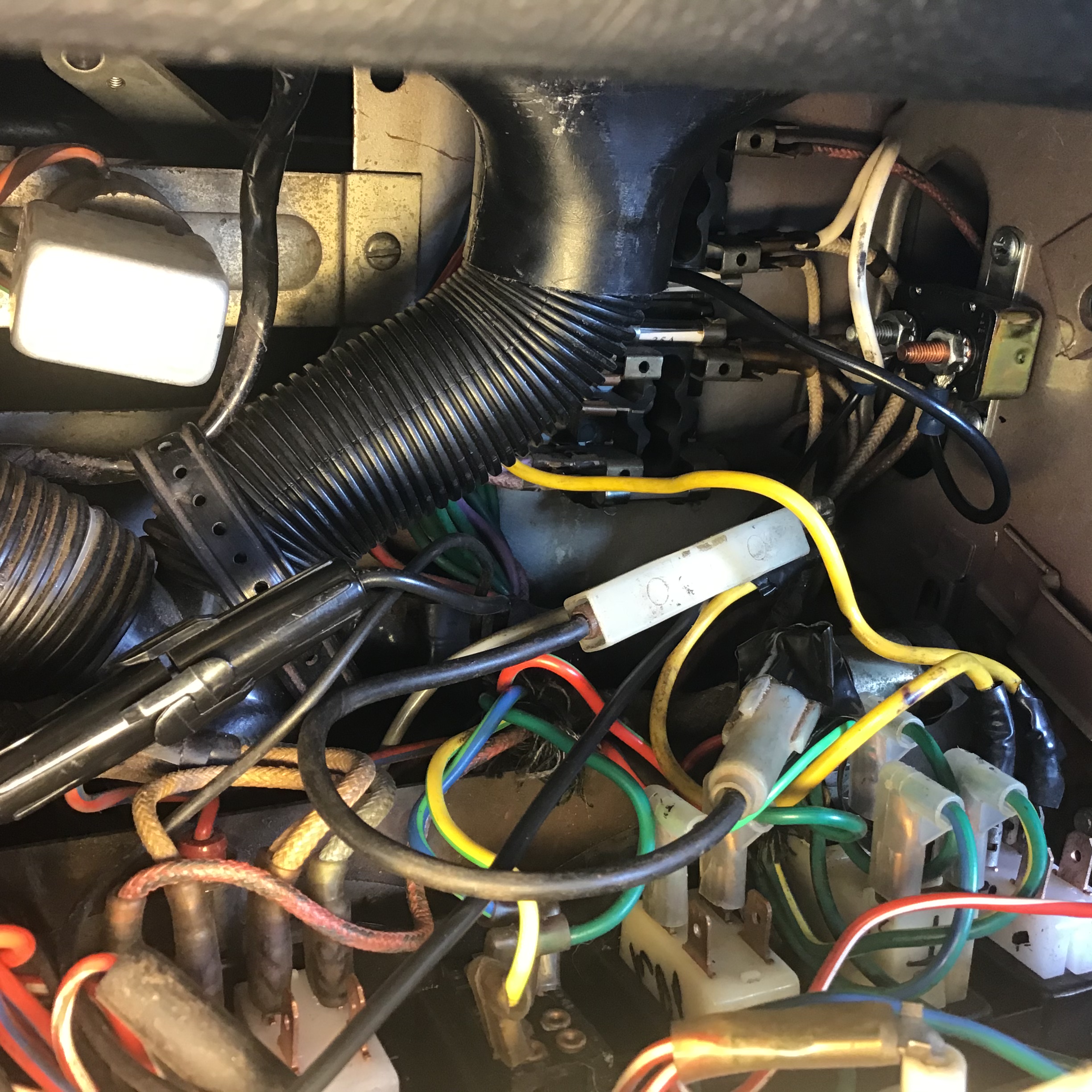
Also, there is no white wire from near the VR to the front. I also remember a green resistor on the fluid bottle heat shield that had 3 wires on 3 different pins. I don’t see these wires so I think that they came from the evaporator that I threw out.
I also included a picture of the relay(?) supplied by Classic Air that is mounted inside the fuse box. One black wire goes to # 6 relay & the other end to the black fused wire you can see lying across the the wiring. This feeds the fan & compressor & is what the a/c guy stated was getting hot.
Q#4. The 1st a/c relay behind the L.F. wheel. When the key is turned on it activates C1; wire is black W/ yellow slashes & is the original fused feed for the a/c. & is live inside the fuse box area. Can be seen in picture. W2, which seems to be a ground.
Also activates C2, faded cloth, looks tan W/slashes similar to feed wire.
Also activates W1, also faded cloth seems white or tan & maybe comes from the fuse box?
I’d once again like to thank you & David for responding & your expertise.
Michael Caro


Sorry. This appeared not as I typed it
Wanted: Upper relay
33252D
To appear separately, next to the individual listings of poles
Looks very confusing. Even now the screen on the right doesn’t appear as I typed, either.
Again, should read:
Lower relay
33232D
C1, C2, W1
These #s & letters smashed up against my listing the pole letters & wires that all should have been in a straight line vertically. Let me know if you would like me to type this info again if you are confused.
Mike
All you should need to do is to run a power wire from the A/C switch to W1 on the “upper relay”. That’s it. You can test that by running a temporary lead from any hot source to W1, the fans should come on immediately.
Amen, gentlemen. Amen.
Thanks.
Just got car back from mechanic mentioned above. All is good W/system. He said those Cool Cat fans pull a lot more air. It’ll be fine.”
Mike