Craig Restores a Series III - Part XIV

SUMMARY OF PREVIOUS THREADS I thru XIII

Part I - Introduction of Hobby Shop and removal of engine/transmission

Part II - Removal of all wiring harnesses, dropping fuel tank, stripping the car of all ancillaries and cleaning asphalt coating from under-body/bonnet

Part III - Engine Tear Down, Removal of Heads, Chrome to Chrome shop, Prep for and actual Painting of the Jaguar

Part IV - A comprehensive matrix of nickel and cadmium platers // Procedure for removing crankshaft // Removing timing chain, guides and tensionor // Repair Timing Chain Cover (aluminum welding) // V12 Exhaust system options // Removal and ultimately Replacing Oil Pump ($$) // Checking Cam Sprockets for reuse // Challenges of removing 6 stuck pistons/sleeves (significant portion of this thread) – including a trip to a machinist; spread over a wide range of posts // Discussion of glass beading and/vs vapor blasting // Return of Chrome

Part V - carbs and dizzy return from rebuild (with contact data) // options for A/C compressor // installed left and right side wiring harnesses and Bulkhead Harness // challenges attaching Bulkhead Harness Grommet (C30670) // Elastrator as a possible tool to solve issue // more on vapor blasting – a definitive discussion // purchased a non-Series III boot lid seal during a group buy to use as a boot lid seal // started install of distributed compressed air from the compressor.

Part VI - processes of wiring new bulkhead harness to the 4x new fuse boxes // variations of Series III Wiring Diagrams // MarekH: Jaguar Wiring 101 // how-to regarding Home Made Circuit Tester for less than $10 // Comparo of newly cadmium bits and tubes to old // rebuilding wiper motor // new Exhaust System // comparo of incandescent bulbs to LED equivalent // camparo of mechanical brake light switch vs hydraulic // tricks to re-installing pick-up/return lines and the ins and outs of the in-tank fuel filter // receipt of all bits to rebuild heads and choosing a machine shop // YouTube videos covering the wiring of the 10x switches on the gauge panel // a source for better than new Front Upper A-Arms (AKA wishbones)

Part VII - the Terminal Post on a Series III is Whitworth (a 1/4 Whitworth Spanner will be correct) and the proper sequencing of the cables // the utility of grounding straps including photos of OEM grounding straps locations // do’s and don’ts’s of applying Dielectric Grease // heads are refurbished – machining done // a schedule of lead times for out-sourced procedures // application of ceramic coating on my fresh paint // definitive identification of Horn Relay Bracket // installing LED panels in brake/tail lamps and front turn signals // a pair of restored Upper Wishbones arrive from Australia // THE definitive discussion of dealing with hydrogen embrittlement on cadmium plated parts //

Part VIII - the need for special washers or rivets to attach side chrome on door // testing fuel sender // installing X-Mat sound-heat barrier on floor pan // receive crankshaft and ConRods back from balancing / polishing // the utility of DEI heat shields // return of ½ the front suspension pieces from cad Plater // Interior Kit receives // the complete solution of the placement of unmarked underfelt pieces

Part IX - applying ACF-50 on aluminum pieces, pressing in Front Suspension Bushings, installation technique for C30670 firewall grommet, stripping radiator cowl. dealing with inner and outer seals on window crank handle.

Part X - assembly of Pistons onto Rods, deciphering A and B pistons vs A and B Head on V12, beginning to reattach front suspension, front horseshoe frame can go on two ways but only one is correct, techniques to plug the air Injection Ports on exhaust side of V12 heads, powder coated cam covers, locknuts vs lock washers, repair options for A/C evaporator and condenser, repair options to rebuild PS rack, A/C compressor replacement options, relay on switches of A/C evaporator, window regulator and various door seals, installing pistons on crankshaft, no need to clock gaps in piston rings, correct version of timing chain tensioner, PDWA install, renewing Radiator Fan Motors, and Bulkhead Layout diagram.

Part XI - how to re-attached hard lines, sources for Belleville Washers, correct assembly order for washers/spacers/etc on upper/lower front suspension, THE definitive discussion about window regulator - where seals go (and where they don’t) - lube points - winder spring - how to insert the regulator - sequence of insertion, Lesson Learned about trusting vs verifying (ref machine shop setting valve lash), dimensions and obstructions for hard wood spacer insert in the bottom of the picture frame, adding a duct fan to fresh air hoses, grounding strap(s), and it’s a tie down point used during shipping not a towing eye.

Part XII - upper and lower door glass stops, applying DEI Heat Shields to Trans Tunnel, importance of cleanliness of regulator spring, Terry’s for long and short PS Rack lines (plan on 3-5 weeks for delivery), orientation of motor mounts (and the challenges of mounting them), installing boot matting and the mat that doesn’t belong on an OTS (lots of photos of original matting), conducting a gas leak test of valves sets, short block → long block, powder coating results.

Part XIII - Sources for Brake Line Kit, trials of 2x small head studs that stripped during head torqueing procedure (biggest coverage), dimension of lower window stop, 1986-92 dead Pedal from RX7 works/fits in Series III XKE, install of duct fans, install of fresh air vents in cabin, items to check on steering column before reinstalling it, reassembly of heater matrix with new matrix, new valve and sealing kit.

2 Likes

In keeping with my efforts to open a Part with good news (which means I’m not gotta even mention head studs right now), I present the first steps in replacing the Rocker Switch Surround (switches and Legend strip)

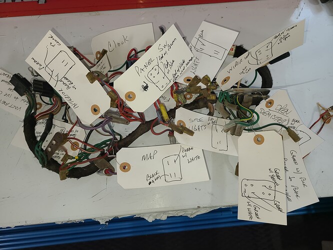
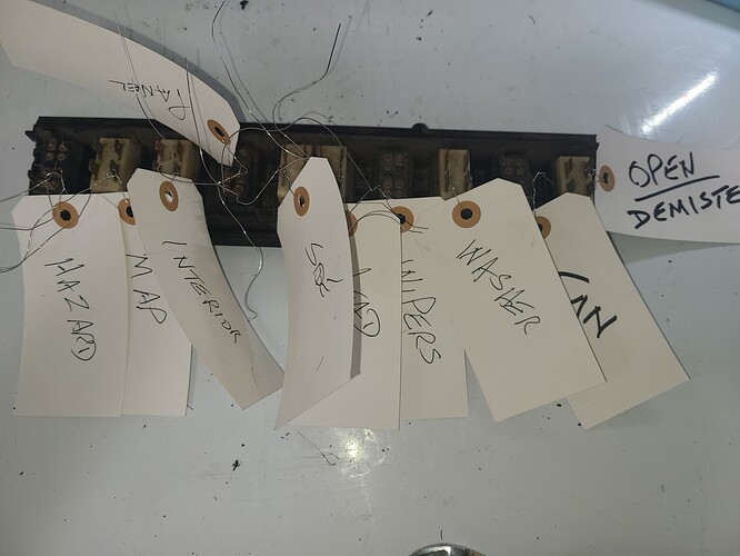
Before removing the rat’s nest of wires known as the dash harness, I bundled and tagged those wires feeding each gauge


and switch

I also have similarly bundled and tagged the wires on the new harness (but enough photos of wires and tags)

That left me with this


Doesn’t look terribly bad. I am considering reusing this vinyl as is - there is only a small bulge at 9-11 o’clock of the clock hole
/
/

The backside didn’t look bad either, but OCD
/

I also ran a die down each stud and attached new hardware to them
/

I then transferred the 10 switches to the new Rocker Switch Surround. I opted for the new surround for two reasons:

  1. My original was missing a goodly amount of the silver trim around each switch opening and
  2. My original was kinda loose

but first I
cleaned the outside of each switch
cleaned the inside of each switch
applied new lube inside each switch, and
used a Dremel to polish the terminals

and after a day and a half

Next came the legend strip. I was concerned about two issues:

  1. damaging the 50+ year old strip (cracking the long, skinny, old plastic piece) and/or
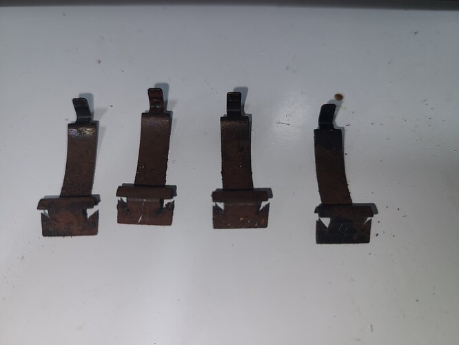
  2. damaging/losing the 4x spring steel clips that secures it to the rocker Switch Surround


/
/
Turns out they only had surface rust on them and all were removed with a small screwdriver to pry them loose . . .

/
/
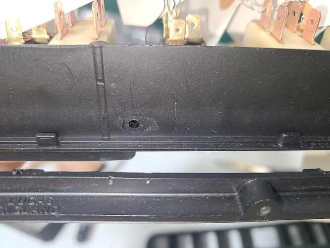
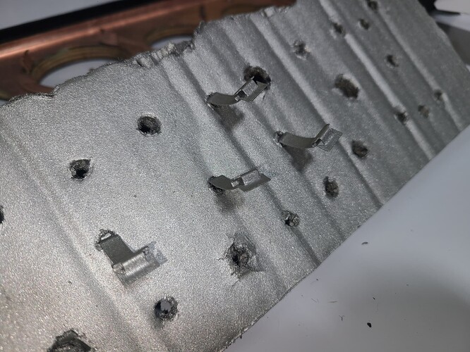
. . . and locating them on the new Rocker Switch Surround was dead easy. There are four pass-through holes to accept the tip and two marks on the ridge below to guide the placement of the clamp feature:

/
/
Now - I ~know~ no-one will ever see them but OCD

/
/

/
/
I’m waiting on the arrival of ~18 LED bulbs and I’ll install the new Dash Wiring Harness followed by the gauges. It’s a toss up whether the bulbs or Loctite Form-a-Thread arrives first

1 Like

That is some impressively Nice work! That takes a lot of time and patience, and you did a great job.

High Praise from a quality source - Thank You, sir.

I forgot to mention that even though transferring those 4x clips was uneventful (for me), care should still be exercised. Anticipating issues, I tried to order those clips in advance. But - I couldn’t find them in the ROM. So I asked my contact at SNGB (Jeremy) if they carried them. No Joy

His reply included this:

QUOTE

This is how the factory book lists those clips…. Very helpful!
UNQUOTE

So - no known part number.
So - don’t lose 'em.
So - don’t break 'em.

Looks super Craig! Did you know that the ghost of the white circle at 2 o’clock to the clock on the backside of the instrument panel had a sticker with a handwritten date of assembly? I still have mine, not in good shape now, with an early 1974 date on it.

I faintly recall that factoid (I knew it held some manufacturing data but lost the detail).
Obviously mine is long gone.

Hi,

I still have mine, and inside the radio console was a similar one with the body number and markings for A/C vs non-A/C (mine) and if an automatic transmission was to be fitted. Also the bottom of the steering column had a similar white sticker with a date written on it.

Cheers!

1 Like

I haven’t seen those others. But there were also identical stickers on the seat back rake mechanism covers. I still have the paper ghosts of those but unfortunately the date is gone.

1 Like

Another follow-up from Part XIII - lower window stops.
As mentioned previously, I only recovered one during my tear-down.


/
/
I have since installed it. Only during the photo-making did I notice I missed aligned it by about an inch too far aft

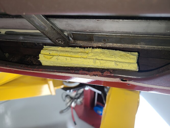
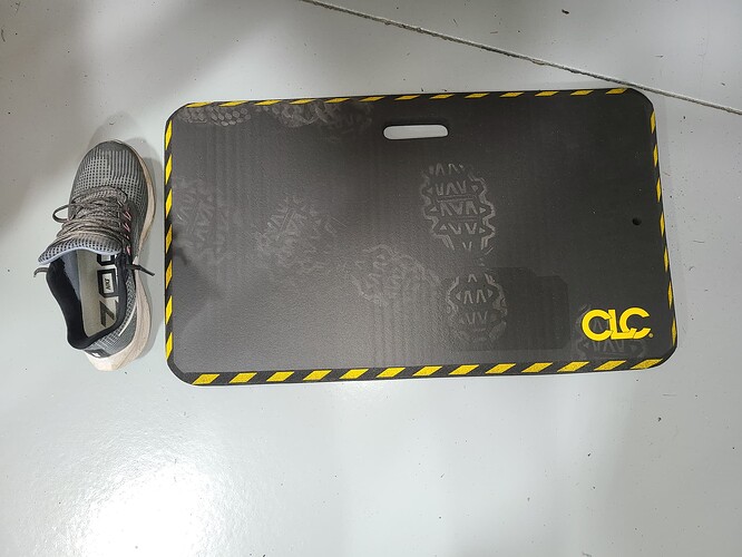
The black line was used to measure the height of a kneeling pad that sacrificed a bit of foam.


/
/

/
/

I glued two pieces together but that ended up being too tall (it stopped the window but there was a sliver of glass sitting proud of the window opening top) so I sliced off 1/2 of the second piece.
You can see I almost glued in too far forward; the regulator just catches the rearmost inch.

I loved that kneepad…:persevere:

Bigger, Thicker and Better alternatives await your next visit


My size 10 for scale
/

And very soft so as to nearly cradle aged knees - nearly an inch thick

It took some searching but I found a right-hand version AND a left-hand version; please don’t mix them up.

1 Like

I adore those Ensolite foam knee pads!

Got a lot accomplished today (TH - 08JUN23).

I bead blasted all 9 of my exhaust manifolds and both Y-pipes in prep for a trip tomorrow to a machine shop with a magna-flux system. I am very skeptical of at least two of the manifolds but will have all of the tested for cracks. I have fingers crossed that I can find four viable candidates on the bunch.

Meanwhile - back at the Gauge Bench:

As mentioned I tagged the old harness while it was still in place . . .


/
/
. . . and similar actions applied to the new harness

/
/
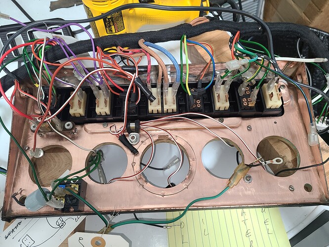
This is about half way through. I intended to start left and go to the right across the entire panel. At about the third fork in the main harness was a bundle of Red w/white wires that power the bulbs in each gauge (wire wrapped at about 11 o’clock on this photo. set that aside and worked inward from each end. Note the Cool Cat (@Michael_Frank) digital IVR waiting its turn in lower left corner

/
/

I took 3-4 still photos of the original IVR and a video to ensure these wires were installed correctly. There is wire stub (Green w/ Black about a foot long that is NOT in the new harness. I had to strip it out of the original and reuse it. It is on the end of the IVR and connects two of the gauges.
/
/

After 3-4 hours all switches are rewired and those wires servicing the gauges lead down their hole. If time permits after the trip to the machine shop tomorrow, gauges go in next. The Green w/ Black wire can be seen running to the right along the bottom 0f the photo


Close up of the 4x switches on left of inverted and up-side-down panel
(Hazard - Map - Interior - Panel)
/
/

Close up of the 4x switches on right of inverted and up-side-down panel
(Wiper - Washer - Fan - Open)

Notes

  • What initially appears quite daunting when replacing this harness ends up not being so bad. Look a the photo of the left half of the panel. The 5x wires feeding the Hazard switch exit the main harness together. The next fork off the main harness feeds the Map and Interior switch. And so on. There are a few times that a wire(s) feeding a gauge exits the main harness with the switch wires but it all sorts itself out pretty quickly.’
    The biggest PITA is the third fork (feeding the Panel switch includes all the Red w/ white wires for the gauge bulbs.

  • The grounding wiring for the gauge bulbs is different. On the original harness, there is a single ground wire servicing the clock. On the new harness, each bulb fixture has a ground wire coming out if it with a ring terminal. I assume this is to be fastened to the horseshoe shaped bracket that secures the gauge in its hole - it has a small stud on the middle of the bracket that is secures with a small nut.


    I assume originally ground was through the bracket touching the copper backing of the panel. This new approach ought to be much better.

  • The Washer Switch (the black switch right of center of above photo) originally had three wires feeding. The new harness has only two. The Green w/ Yellow and the Green wire match old vs new. The original harness included a Green w/ White wire on the naked tab in the lower right corner of the switch.

  • The harness is a perfect match to the original (with the above exceptions). Color coding is perfect, the size/type of connector is proper, and the whole thing aligns perfectly with the original. I have found 3-5 instances where the new wire is too long by an inch or two (better than the alternative) but may be an issue when I try to fit the whole panel into the dash. The extra length x5 may be a nuisance. So far just 1-2 wires that look too shirt but they service gauges so will know more later.

  • Be careful using ID tags with wires to fasten them. I stuck myself 4 times on the running end of those suckers. @Wiggles will be happy that blood was shed (OK - maybe just a drop or two each time).

  • One of the issue rarely discussed that may require me to replace a switch is NOT the locking tab that broke off (all of mine are intact) or the lost innard bit BUT the metal terminals on the back of the switch that the new wires affix to. I have 2 or 3 that likely will not survive another event of being being bent flat. Some the wire terminals were very tight when fitting onto the switch

I’m sure I forgot something, but will edit this post it I remember it

1 Like

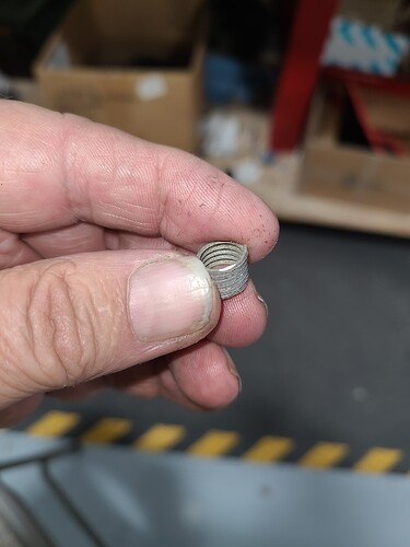
At the very end of Part XIII, I extracted the second of two studs that pulled aluminum out. @angelw said:

Bill - I put a magnet to the new coil of what I am sure is aluminum. If a Heli Coil, it would have attached to the magnet and it did not.

And I used a point file an made two light passes across the coil.


Pretty soft metal; it removed a part of the 90° edge of the coil easily

Go figure . . .

Look for a small bag of miscellaneous wires that should have come with your wiring harness. That’s where I found that little sucker in my harness kit.

I’ll be damned.
I only have 1-2 unopened bags that deal mostly with with wiring for the fuel pump / boot.
But I’ll surely look in the AM
Thanks for the tip

Not so Craig. Heli Coils are Austenitic Stainless Steel and therefore, non-magnetic. Test it with a file.

Regards,

Bill

We used some Helicoils to repair Craig’s cam, and they were magnetic. Odd.

What am I looking after I scrape the coils with a file?
If a magnet test is inconclusive, what then/

No Joy, Doug.
I reused the original. Shouldn’t matter a great deal.
See below