Unusual two tone combination ![]()
Steve
Yes, we are talking about the same pieces. I appreciate the offer but mine are still usable.
So, what I have is a new Bell system that goes forward from the 4x outlet whale tail to about the transmission and the two likely original Y-Pipes. What I am looking for is either a set of manifolds or a set of headers to connect the exhaust system to the heads.
Thanks for the head’s up regarding the spacing difference between the original system and the headers.
Craig
Craig
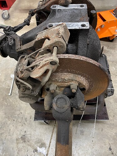
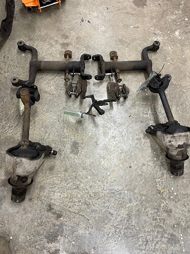
No update postings for 2 weeks, I am getting worried about you. I have moved on from engine building to a complete overhaul of an IRS in need of help. I am saving the bodywork for when I have a more concentrated period of time to really get into it rather than trying to do it in bits and pieces.
Hope all is well.
Rod
No need to worry – life just got in the way
Understood, it has interfered with my Jag work too, but right now I am struggling with rear suspension U joints covered with 40 year old grease so work is sounding better by the minute.
I just wrapped up a very enjoyable and productive visit by fellow-forum-member @REBUILD61OTS Danny who is on a protracted globe-trotting trip gathering info, leads on rare parts, and photo-taking of 1961 XKEs. He has a very early example (flat floors and welded louvers but his example was built 1 month too late and does NOT sport OBLs).
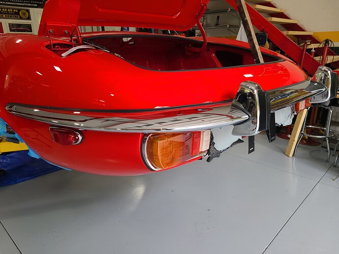
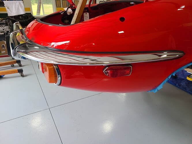
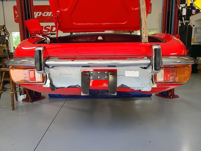
He spent some time with @Wiggles and then drove south for a visit with me in the Springs. As we coordinated his visit, I coyly asked if he’d be willing to be the 2d man on the two-person job of assembling and installing the rear bumper assembly on my Series III. He readily agreed.
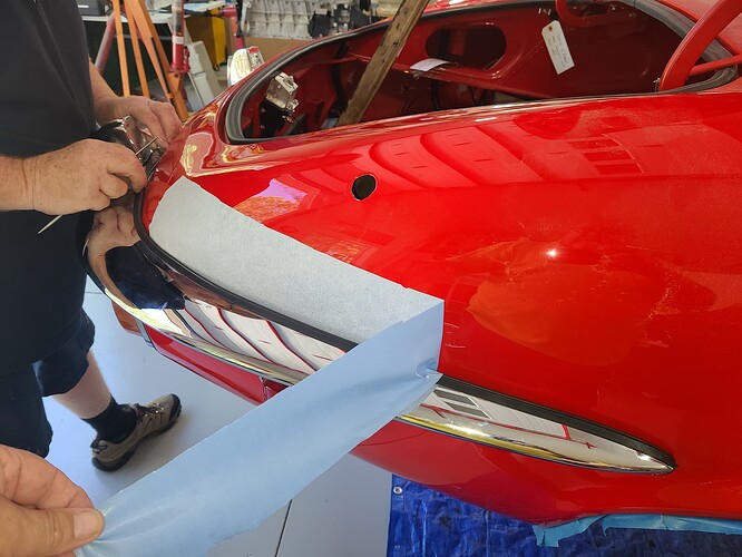
Up first, layer on some 3M self-adhesive protective stuff to preclude small scratches in the paint.
https://www.amazon.com/dp/B099G5GRGW?ref=ppx_yo2ov_dt_b_product_details&th=1
I failed to take a photo of that but here it is being pealed off. Note how it is strong enough that it pulls out from behind the attached bumper without tearing or leaving scraps behind.
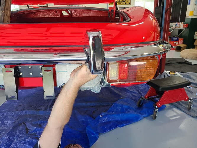
The next part was piecing together the three elements of the rear bumper. I may have been coy in my request for help but Danny was NOT shy about digging in. My lack of photos of the removal of the assembly caused us to take a wrong turn and cost about an hour to back track and regroup.
/
/
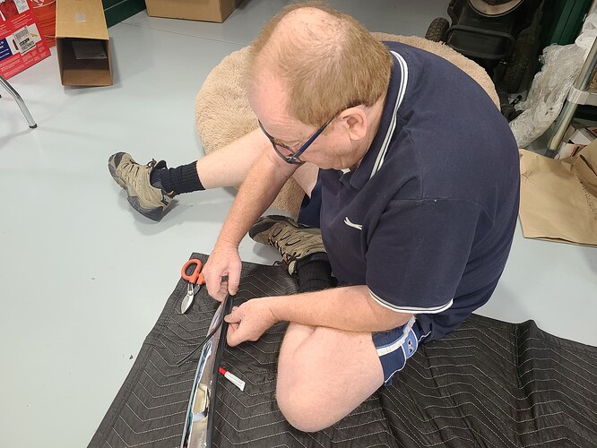
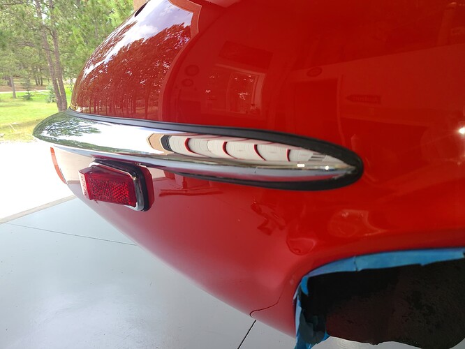
After getting the bumper sections properly assembled, then came the fun of attached the body seal. Daps of SuperGlue proved quite handy.
The efforts to attach to the rear bumper in a single go were derailed when Danny asked me where I kept the bumper bolts for the side sheet metal. I replied: “This one?”
Danny: “There are supposed to be 2 and both attached (rivetted to the inside rear fender wall (in the boot)”
Whether I lost one, one was lost by the Phoenix-based body shop in 1992, or I misplaced one to be discovered months from now, was irrelevant. They needed to be attached prior to paint.
Put down the wrenches.
.
Road Trip: Ace Hardware.
I purchased 2x bolts (3/8-24 1.25" long) and washers.
Back to the Hobby Shop to weld the washer to the bolt and then slather each with JB Weld. Then we placed them in the respective hole to cure over-night.
The next day, the bumper should have been installed in 35 minutes. While making the final adjustments and tightening the bolts,
I stepped back and commented how the over-riders looked bow legged.
There is one part number for them so I assumed it didn’t matter which went where. WRONG. I had tagged them L or R when I removed them but the tag was removed for chroming. Attention to detail, Balzer.
So we swamped them with the bumper in situ. Tough going but much easier than removing the whole assembly and starting over.
/
/
/
/
/
/
The fit of the bumper and body seal met @REBUILD61OTS 's approval:
I felt I had flogged Danny enough (given his was supposed to have been a 1-day visit) but he said:
“So – what’s next?”
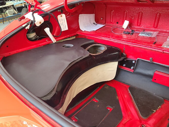
Me: “Wellll - - the fuel tank is always a trick to install”
No amount of photos or discussion is sufficient.
BEFORE:
AFTER
/
/
No words can describe the procedure (they ALL would be censored anyway).
No words are adequate to articulate my thanks and appreciation to Danny - he did 80% of the wrestling and wrangling to get it in and secured. All at the cost of a steak dinner.
Danny – THANK YOU.
All the best in your search for early (first 250 RHD E-Type) bits and parts .
You certainly have accommodations during your next trip from Aussie to the States for as long as you please.
Now – about the rebuild of my IRS . . .
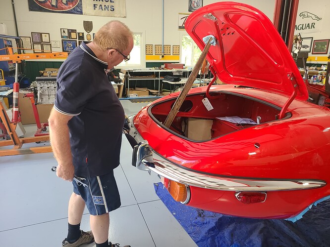
PS - I DID bemoan my painter / body man on numerous occasions for installing only 4 of the 7 boot lid springs on each side. That wooden brace was ALWAYS in the wrong place.
Didn’t realise how bald I am on top😱
I have found through the years after working on 7 Jaguars, NOTHING takes 35 minutes. The simplest job takes way longer than I anticipated.
I was sorta kidding with that comment because on Day 1 (while we were discussing other jobs he could help with after the rear bumper was installed) Danny offered to teach/lead/assist/guide/do-it-himself the disassembly of my IRS. He has rebuild 4-5 IRS’s.
During his last hour at my place, he took the time to articulate the detailed step-by-step procedure to disassemble the IRS. He included a focus on dummy shafts, locations of safety wired bolts and where to take detailed notes/photos when spacers / bearings / and such were about to emerge.
AND – with my upper steering column in his lap for almost 11 seconds, Danny identified my need to
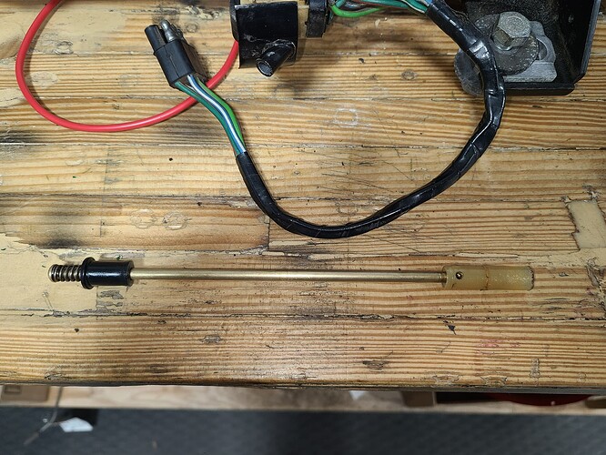
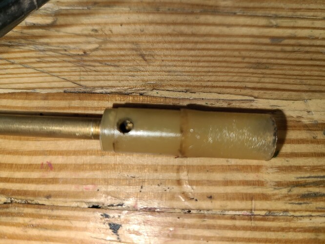
- replace to horn push rod assembly (left untouched, it is likely my horn would have continuously sounded)
- replace the upper and lower bearing on the column as he sensed some dirt/grit causing a small bit of drag while turning the shaft
(both rebuild kits are offered by Barratt’s)
Danny is not only a superb mechanic well grounded in all things Jaguar (he’ll admit a paucity of knowledge on the particulars of Series IIIs), he is also adept at spending my money – ![]()
Craig
That is some real progress in a couple of days.
Speaking of IRS, I was working on mine today, sadly with no Danny (or anybody else) in sight. I hope your U-Joints are not as stuck as mine are.
Rod
Craig
Just did a rebuild job on my IRS due to having to rebuild the brake calipers. Pretty much straight forward wrenching. Keep track of all the spacers and where they go. I used lots of twist ties and cable ties to keep thing where they belong. Differential was in good shape so no issues there.
Danny is a true gentleman and quite the experienced restorer. I really enjoyed my time with him.
I am not expecting many issues with the IRS. I had it rebuilt in the mid-80’s (except for the pumpkin) so it should come apart without fanfare ![]()
![]()
Hello Craig,
What part of the Horn System are you referring to having to replace. It’s seldom that the telescoping brass centre rod and tube need to be replaced, but common for the Horn Contact sleeve on the outside of the inner steering column. If it is the Horn Contact sleeve that is the issue, then I know for sure that SNGB don’t have the correct part. The part in the package that has the correct part number for the S3 is in fact incorrect. I’ve just been dealing with this for two steering columns in recent weeks and at the end of the day, was told by SNGB that the part is no longer available…
If it is the Horn Contact sleeve that has to be replaced, the original part is difficult to assemble on the insulator that sits between the bore of the sleeve and the OD of the Inner Steering Column. I made up installation tolling that made the job reasonably simple and I can’t see it being done without such tooling.
My resolve to the original Horn Contact Sleeve not being available was to make my own. If you find that you can’t get one, I can help you out.
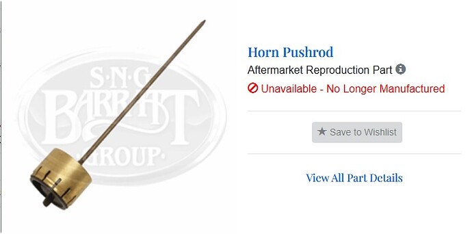
The following picture show the complete Horn Pushrod assembly as no longer being manufactured,
but the repair kit (following picture), part number SBS1279 as being In Stock.
However, what you receive in the Repair Kit is incorrect and has less than a snowball’s chance of survival in Hell, of being able to be used.
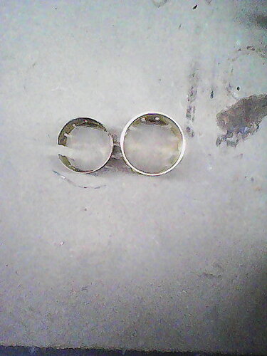
In the following picture, the Horn Contact Sleeve on the Left is the original part, with the replacement part on the right. Eyeball measurement is all that’s required to determine its not going to fit.
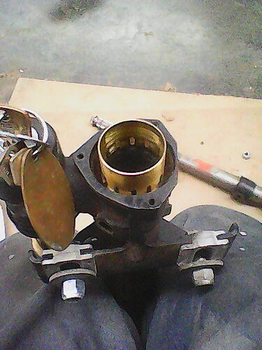
The following picture shows the fit of the Repair Kit Insulator and Contact Sleeve on the Steering Column. A Dick in a Shirt Sleeve is a fairly accurate description of the fit. It should be an interference fit.
The following picture shows that the Contact Sleeve supplied in the Repair Kit is way to large in diameter to even fit inside the Outer Steering Column.
What was sent to me next was Repair Kit SBS1280. This is a Repair Kit for a Series 1 E Type and way too small. When I reported this, I was told that the diameter of the Horn Contact Sleeve in the Repair Kits for all Model E Types (only S1 and S3 cars use this system with the horn push button in the centre of the Steering Wheel) are the same diameter. Clearly that is not the case, for I had kits where the Contact Sleeves were 1/8" too small, and 1/8" too large. Ultimately, I was told that the correct Repair Kit for the S3 car is not available.
With regards to the bearings, the original mini taper roller bearings are not available. SNGB offer solid brass replacements. I made a set out of bearing bronze and wasn’t happy with its performance, so I doubt that brass units will be any better. I now use a material called Turkite, a heavy loadbearing, antifriction material used on the Slideways for many machine tools. In my opinion, replacing the Taper Roller bearings, whether they are damage or not, with Turkite is an improvement.
With the bearing replacement system supplied by SNGB, machining is required. With Turkite, it simply replaces the Taper Roller bearings. It can tolerate the moderate brinelling that is common to be seen on the steel bearing surfaces. However, to re-machine these surfaces to a true and smooth finish is reasonably easy as they can be easily removed from the Steering Column Housing.
Regards,
Bill
Hello Craig,
Are you going to rebuild the Differential this time around? If so, the bearings for the output shafts have not been available for many years. The original bearings were double row, angular contact, with the centre race slit into two halves. When the bearing is assembled and the centre race held in place hand tight, there is a gap between the inner faces of this race. When the bearing is assembled on the Output Shaft and the securing nut torqued up to spec, the two halves of the inner race are pressed together until their inner faces are in firm contact. At this point the bearings are in correct pre-load.
The alternative being offered by the parts sellers is not a good alternative. It’s 2mm narrower, requiring 2mm spacer to be used. The inner race of the available bearing is NOT split, not pre-loaded, nor is it possible to be pre-loaded. The best solution is to replace the Output Shafts and Retainer Plates/Bearing Housings with those from a Series 2 onwards XJ6, or any XJS Salsbury differential. They are interchangeable with the Output Shafts and Retainer Plates of the E Type without any modification whatsoever. These alternate Output Shafts and Retainer Plates/Bearing Housings use Taper Roller Bearings that are readily available. I can supply the alternate Retainer Plates/Bearing Housings new and the Output Shafts on am exchange basis.
Regards,
Bill
Thanks to the precious help of Bill and others I have solved the problem of output bearings a couple of years ago, having replaced reconditioned shafts from a XJS, which I got from a supplier in the UK .
Documented on an earlier post .
Good luck with the IRS .
Rui
Bill, you said: “What part of the Horn System are you referring to having to replace? It’s common for the Horn Contact sleeve on the outside of the inner steering column.
I won’t know if the Horn Contact Sleeve is the culprit until I further disassemble the column.
My resolve to the original Horn Contact Sleeve not being available was to make my own. If you find that you can’t get one, I can help you out.
I’ll certainly take you up on that when I dissect the column to see what it what
This is a recreation of the test conducted by Danny:
Multimeter to set to “Alarm” when circuit is closed. Details in captions
/
/
/
/
/
/
from your image above
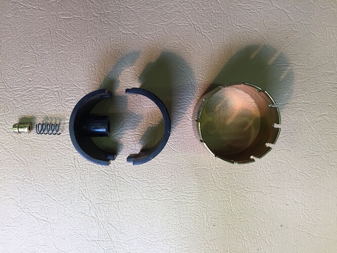
I think I’ll need the small spring (C8156), the e-clip (not shown), and the plastic halves (C29773 and 72)
EDIT - I posted a 15 second video on YouTube showing a peak of the condition of my Horn Contact Sleeve: (which I haven’t been able to get to in my dissection of my Upper steering Column).
EIDT II: I found a series of Photos on the forum of the Upper Steering Column. This one captures what I believe to be my problem
These parts (shown below) in an exploded view
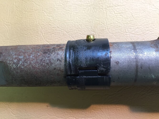
and here on the column
haven’t been unearthed as yet. The small spring (and the brass nipple) apparently are AWOL
I suspect (hope) that the missing spring and small bits is recoverable once I open up the column - but I fear the worst. Not knowing the horn rod moved so easily, I managed to pull it totally out of the column when I was expanding it to clean the congealed crud and stuff of the column splines. My hearing is bad but I ~may~ have heard “something” hit my bench when I did. I didn’t know what to look for and that event was weeks ago.
With regards to the bearings, the original mini taper roller bearings are not available. SNGB offer solid brass replacements. I made a set out of bearing bronze and wasn’t happy with its performance, so I doubt that brass units will be any better. I now use a material called Turkite as an improvement.
I found this write-up on Google:
Turcite ® A is a self-lubricating Acetal-based thermoplastic bearing material. Turcite ® A is suitable for moderate to heavy loads at moderate speeds. It performs well under vibratory and dynamic loading and is readily machinable. It is recommended for a maximum continuous service temperature of 180°F (80°C). . .
. . . and I will be ordering some.
Available here: Turcite® B | Machine Tool Groups
They advertise no minimum order; I reckon I’ll need a 2.5 x 7.0 cm piece? (See next post)
Hello Craig,
Are you going to rebuild the Differential this time around?
Yes
If so, the bearings for the output shafts have not been available for many years. . . . The alternative being offered by the parts sellers is not a good alternative. It’s 2mm narrower, requiring 2mm spacer to be used. The inner race of the available bearing is NOT split, not pre-loaded, nor is it possible to be pre-loaded. . . . The best solution is to replace the Output Shafts and Retainer Plates/Bearing Housings with those from a Series 2 onwards XJ6, or any XJS Salsbury differential. . . . I can supply the alternate Retainer Plates/Bearing Housings new and the Output Shafts on am exchange basis.
Again, I will avail myself of your kind offer (when I get that far). Perhaps you’d be so kind to include an appropriate section of Turcite . . .
Separate topic: I was told:
“The Dana 44 clutch pack (Dana P/N 22233X) is the same as Salisbury original. “
Can you confirm this statement?
In any event, I will have the innards of the differential professionally rebuilt. @Wiggles recommends a quality shop in Denver to do that part. I will tend to the axles, disc brakes, and the attendant washers, spacer, and bearing sets myself
[quote=“Craig_Balzer, post:38, topic:436062”]
Hello Craig,
There are two springs in the Horn System, those shown in the two pictures above; neither of which can be lost by removing the rod assembly shown in the top picture.
The picture immediately above is not of components from a S3 Steering Column, but the parts are similar.
The video shows the Horn Contact Sleeve intact. Frequently, where the Copper Contact Pickup runs on the Contact Sleeve, the Sleeve will be worn through to the insulation. In this case the Horn won’t operate in the area where the Contact Sleeve is worn through. Although not worn through, you will probably find a band on the Contact Sleeve, as wide as the Copper Contact Pickup, that is quite worn. In this case, the Contact Sleeve should be replaced.
The Contact Sleeve being worn through won’t give you the short that you have, and the Thin Brass Sleeve Assembly looks OK. It could just be a lot of conductive crud inside this brass tube that the Rod locates in.
Regards,
Bill
