Car 1985 XJS Cabriolet 3.6 ( Flat Air box ) ECU – DAC3831 ( MAP internal )
Engine Symptoms in the beginning:
1st Hard to start and then won’t start (Sounded hydro locked)
Fuel pump would not prime (run for 3 sec key on)
Found fuel in oil & manifold. Engine spewed up mix when cranked.
Some injectors found to be staying on (Fuel rail pulled back off manifold & engine cranked)
FIRST TESTS or REPAIRS DONE
1: All Injectors sent for Sonic Cleaning
2: ECU sent for testing at APT Electronics
(Passed after two days testing)
3: drained oil fuel mix / Cleaned out Manifold & AAV pipes.
4: Only one pin of injector boots with 12V found on across all 6 injectors
(Checked loom & renewed all injector loom terminals.)
5: Inertia Switch wiring to main relay & function checked ( All good )
6: Fitted new Fuel pump (original failed)
Engine State after 1st Repairs
Car if started is only with Injector resistor pack disconnected.
(When fully warmed up could turn off, connect pack and engine could be started)
Fuel pump would still not prime (run for 3 sec key on)
Neg. wire jumped to orange wire on Fuel Relay to enable pump
Now only 12V on the Pink /black wires….and 0.51v on the Orange /Slate & Orange/ Green
(The first few starts I had 12Vs on both pins)
TPS wires found to broken
Fuel found in some Cylinders
a. spark plugs removed& then engine cranked
b. Resistor pack connected, key on – some injectors staying on (viewed via spark plug hole)
Continued…
SECOUND RUN OF TESTS or REPAIRS DONE
1a: Pressure gauge fitted inline to fuel rail (2.5Bar 36psi) no leaked down with injectors disconnected.
b: Injector pulse generator test on pressurised rail, no injector stayed on or leaked down.
(Resistor pack disconnected)
3: Fixed TPS wires and set to 0.32V at closed throttle WOT 5.10v
4: Checked all wires & wiring (For Continuity -Fault to Grd-. or Pos.+ done from the terminals for the Resistor Pack, Injector Boots & Injector loom to ECU Pins while disconnected at both ends. (All good no shorts found)
CURRENT Engine Symptoms:
Fuel pump would still not prime (run for 3 sec key on)
No Engine Start
Injectors loom Plugs Now only 12V on the Pink /black wires….and 0.51v on the Orange /Slate & Orange/ Green (The first few starts I had 12Vs on both pins)
Did test for Short Of Grounding
Ground found on injector wires from ECU to Resistor Pack wires (Orange /Slate & Orange/ Green ) should be 12V :when key on
Fuel Pump: Either APT missed the known but uncommon issue in the fuel pump grounding circuit, or there’s a wiring problem between FPR and ECU. Best to check continuity on that circuit, and probe the FPR Control pin from the relay socket for grounding with key on. Ideally this would be checked on the pin AT the ECU.
Extra Fuel In Cylinders: Check the FP Regulator for a blown diaphragm - fuel leaking through the vac tube. This would explain having NO leak/hold-on problems with the injectors, but extra fuel in the cylinders (although I’m surprised pressure is maintained that high).
With injectors & ECU disconnected, check each injector control wire pathway to be open circuit (should be all open circuit). Check Power Resistors for proper Ohms across pins. It almost sounds like there is a problem in the resistor pack and that there’s an internal grounding allowing the injectors to turn on, and preventing the ECU from controlling the “hold” phase of injection. Don’t’ keep running the car w/o a good Power Resistor pack. I’ve heard it over-taxes the ECU to run the injectors in “peak” high current phase w/o being able to switch to the low current “hold” phase.
With all injectors disconnected & key-on you should have 12V ONLY on the pink-black wires. The other side - control grounds to the ECU should all be dead/open as far as I understand - until the ECU switch’s the transistors to ground turning on the injectors. IF you have even one injector connected, power flow through it to the other side (with a small voltage drop) bringing the other wires high as the control circuit is fused inside the ECU (even though injectors are wired in sets of 3).
It would be worth double checking that the injectors Ohm to spec (usually about 2.4 Ohms).
I’m basing all this off of the 6CU for the V12- which is essentially double an 8CU for the I6 (so I understand).
The broken TPS wiring probably didn’t do much as long as it was on the potentiometer side - as the ground for the CTS is wired in on the harness side - shared with the TPS. The TPS does 2 things: 1. tells the ECU the throttle is closed at idle, and then gives the ECU a throttle change delta for enrichment like a carburetor’s accelerator pump.
Hi Paul K,
Thanks for you response .Spent yesterday going over injector circuit wires form ECU to Injector Plugs mainly checking for shorts or grounds.
Test found constant ground present at ECU Pins 30 PINK/GREN & 12 PINK/SLAT wires which go to Resistor Pack which feeds INJECTOR Plugs Left Pin wires ORANGE/GREEN & ORANGE/SLATE. Injectors loom Plugs RHT PINS 12V on all the Pink /black wires….and LFT PINS have 0.51v on the Orange /Slate & Orange/ Green wires from Resistor Pack ( Pack ohms are In Spec )
I’m con fused…many forum write ups state for V12s state: 12volts should be present at both pins of injector Plugs
Ok, was this tested THROUGH the Resistor pack? (suggesting a short to ground in the Resistor pack) or TO the ECU suggesting either a rub-through in wiring to ground on the “HOLD” circuits, or an un-found problem in the ECU holding the circuits “ON” (According to AJ6 re the 6CU a failure in the flyback diode if I recall). It might be worth checking the ECU’s pins 30 & 12 to ground to case w/o any power. It SHOULD be open circuit w/o the ECU commanding the RCA transistors. (This would only tell you if there’s a passive failure to ground).
I’m not sure why you’d see 0.51v on the control side of the injectors except for enough backfeeding of voltage & resistance.
YES you’d see 12V on BOTH sides of the injector pins ONLY if other injectors are connected allowing the potential to pass through the injector coils into the other side of the wiring (Orange/#color ground control side).
Think of the dual ignition coils on a V12. A white power wire goes to both in parallel, and there’s a ground side controlled by the amp. W/power on, you see 12V on both sides of the coil. If you disconnect the ground side on ONE coil, you stills see +12V on the ground side of the other coil (because it’s actually open circuit having not yet been brought to ground). The amp grounds the coils (charging them) - or opening the injectors in the case of the ECU - then when the amp releases the ground going open circuit, a spark is triggered in the ignition coils ( or injectors close & a little flyback voltage is also created).
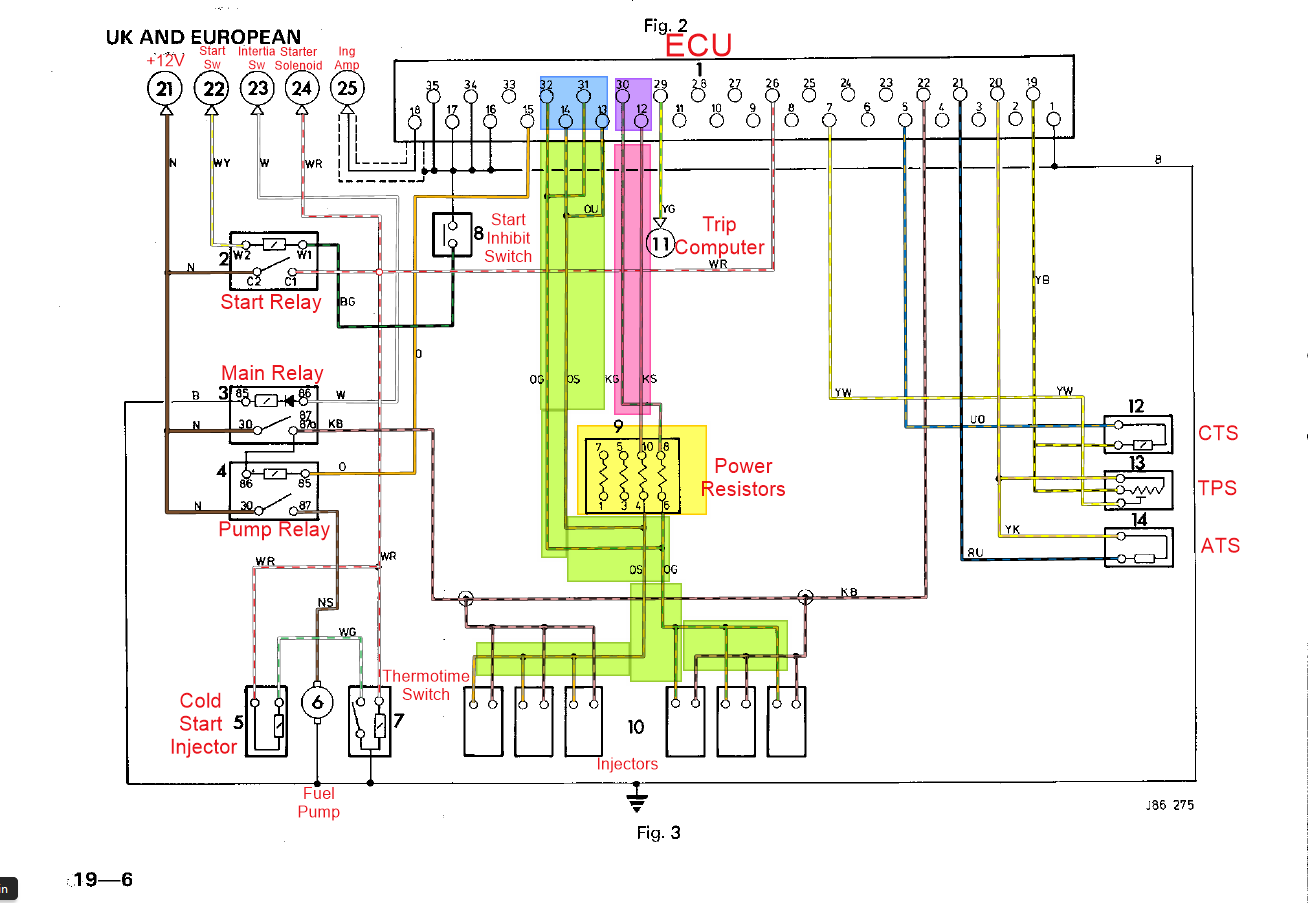
If you look at the diagram above and visually trace the pink/black common +12V circuit to all injectors, you can see that with the Orange/color control wires disconnected, they’d simply be connected to the ECU (only) and should appear dead/open circuit w/o the ECU providing the ground pathway… BUT! If a single injector is connected, the +12V passes through the coil, into the entirety of that Orange/Color control line, - and if it was like in the fused internal circuit of the 6CU, back up the other Orange/Color control wire since the channels in the ECU are fused. There would be some small voltage drop because of the resistance of the injector - diminishing with more injectors connected in parallel.
Photo from another post. 8CU pins labeled. You can see how the open, and hold circuits are fused (separately) inside the ECU here: So really it’ just a single open, then a single hold circuit… but split into 2 Orange/color control wires coming out of the ECU.
To be clear, I’m suggesting checking these circuits disconnected in isolation from each other to be sure all are open-circuit to ground (normal). Of course with the ECU disconnected, those wires become separate circuits rather than fused by the ECU (so if there was a rub through to ground on one- but not the other - you’d find it).
Thanks Paul…I’ve been unplugging injector boot and doing test …( I’m losing it !!) I think you’ve just saved me sending ECU for another test. when rain stops Ill put ECU back and then back probe new injector boots while connected to injectors.
THE PLAN
1: Check for 12Vs connected Injector harness Back Probed
2 : Check for Voltage back to Resistor Pack
3: TPS Check ( fitted washers behind bolts to stop slipping back while tightening down, Left back probe in so I could check while running. Set to 0.32v came back day later at key on reading 0.31v. Turn throttle capstan a few times it then flutters between 0.31 - 0.32v
Thanks for the ECU , FUEL INJECTION ( UK Europe ) HARNESS,CIRCUITS & COMPONENTS image. my version attached here.
My concern is that there might be a pathway to ground in the control side of the injector harness circuit independent of the ECU which is both holding injectors on when they get power - and preventing the ECU from commanding them when the Resistor Pack is in place - suggesting that problem is either in the resistor pack OR the wires from the resistor pack to the ECU … OR the ECU hold circuits. That’s why I’ve suggested testing each circuit independently and disconnected from power and each other.
The ECU sends a 5V input through the TPS as it’s reference voltage, and the TPS is just a potentiometer - i.e. simply a voltage divider, so you can easily calculate the Ohms it needs to see in order to have 0.32V at idle. It’s 4K Ohm wiper so:
Hi Paul & Rob
My FP Relay and Main Relay are both in boot next to ECU on Wheel arch in Wing .I did continuity test a few days back …checked out ok. I just checked oil ( fuel present ) then realised that the bores might have been washed clean over days of cranking. So pulled spark plugs and oiled all six pots cranked engine for 5 seconds and then oiled again . Replaced spark plugs, cranked ,she caught for a few second …then I realised I had no fuel pressure ( Have a pressure gauge set inline to cold start injector)…out of FUEL!! ??? Clamped off fuel filter either side , heard air escaping ,hardly any fuel in filter. Unclamped mini sump side hose & jumped fuel relay…spluttered like straw in empty cup. Just waiting for a ride to get fuel.
1:Yesterday Engine spun too freely and wouldn’t fire ., suspected bores had been washed by continuous cranking. I did a Compression Test the results CYL = Psi 1 = 150 2 = 170 3 = 210 4 = 250 5 = 200 6 =160 : Oiled bores over night and checked today ( wet bores) got 250 -240 across the six cylinders.
2: Installed spark plugs checked TPS , cranked… nothing …held throttle open slightly and started up. Sounded like she was struggling for air , checked AAV air ways circuit …then replaced started on the button:
3: Ran until warmed up… ran round block stalled a couple times but restarted when gassed on crank. Got home and adjusted Idle to 850rpm , found that disconnecting air temp sensor made for easier restart while warm.
4: Let the car cool down 45mins , would not restart then engine locked. Pulled sparkplugs and cranked several pots flooded.
5:Heard large CLICK in engine bay every time key turned to KEY2 position…decided to investigate . Pulled injector rail out manifold , left electrics connected, When I turned 2 to KEY2 position all injectors came ON and STAYED ON !!
6:Checked injector loom for ground fault nothing seems wrong.
Planning to go boot to injectors checking the wiring, Hoping it not a Fault with the ECU.
Unfortunately sounds like it is…if loom isn’t shorted to ground, ECU must be grounding them.
Common on the 6CU controller used on the 5.3; don’t know about the AJ6
Easy to check:
Disconnect the ballast resistor and see if it’s shorted.
Unplug the the ECU and the injectors and check for continuities and shorts between the ECU plug and the injector plugs.
You might want to see what the control side pins look like when probed for connection to ground with key-on and NONE of the injectors connected. I’d imagine there HAS to be a connection to ground there to turn the injectors on - but the question remains is it in the ECU? It sounds like it if you see nothing but open circuits on those wires with the ECU and Injectors disconnected. IDK how this could be intermittent but…
Also check your ECU’s grounds … ECUs can do weird things w/o good grounding. The Elec Guide PDF for the year shows all the ground locations. The one in the trunk is very important. Adding an extra strap between Engine & Frame has been known to help reliability (various issues), and there are other engine bay grounds (as noted here):
UPDATE 2
Got a replacement ECU Cleaned Plug PIN connections on unit, plugged in -KEY 2nd position ( fuel pump primed…Hooray!!! ) Checked injector rail (Pullout from manifold )…they were not stuck open.
Cranked engine a few times and the injectors went back to being grounded at KEY 2 on position. Checked all wiring …injector harness ,harness to ECU while disconnected from each other for grounding short …nothing.
Everything connected apart from ECU …correct voltage at injectors, resistor pack and harness plugs.
Could it be a sensor? that’s telling the ECU to fire injectors at the KEY2 position…TPS ( Throttle Position Sensor ) I had to open and fix broken wires. Bench tested with 5v supply and got good output readings on multimeter 0.28v -5.10v.Put TPS on car and had it set 0.33v and got engine running.
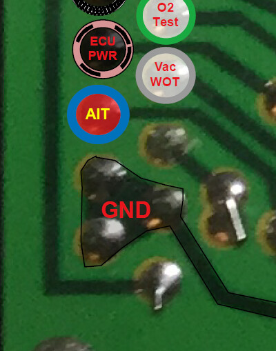
I opened ECU plug to check wire all looks good and no continuity issues. Only thing I noticed is my GRND is on pin 2 not pin 1 ( see images
(SEE EDIT BELOW- Initial diagram is wrong & associated assumptions wrong - on of my old versions …)
I think you have your connector numbering backwards. Check again for shorts w/ the opposite layout:
(Sister ECU’s numbering from that view of the connector). BTW the numbers should be imprinted in the connector body if I recall from the TE connector PDF.
There’s no sensor I can think of that would cause the ECU to HOLD injectors on. The car will run with the TPS entirely disconnected for example. An intermittent short could… and weird grounds/bad ground have been reported to cause very unexplainable things. Adding a ground between engine & body is also always a good idea. You can sim that with jumper cables to test (really reaching here).
~Paul K.
EDIT> Never mind… I see your connector cables come in from the other direction. I’ll have to look at this… something seems off here.
Ahh damnnit… here’s the RIGHT diagram (an updated one I had fixed for orientation)
So hmm… you are correct in your numbering. Well… that’s different… So either Jag’s diagram is wrong (not unheard of)… or… it’s worth cracking the ECU cover & seeing where Pin 1 goes.
HI Paul , there is nothing in PIN 1…my car and full ECU details DAC3831 8cu are below.
Vehicle: 1985 Jaguar - XJS 6 cyl - 3.6 litre
Car is Cabriolet ( Targa roof panels ) All these earl cars started off as coup body’s & V12 elements before conversion .
Many years ago I made a test circuit for my 1984 3.6L & repaired the
ECU. I still have the test circuit & may be able to remember how to use
it! I’m in Brighton UK.
It’s a long time since I built it, but it simulates all the sensors &
circuits exterior to the ECU. It needs pulses from the ignition (I used
a signal generator) & needs a oscilloscope to look at the pulses to the
injectors (a node light might do this).
My engine wouldn’t cease when hot, but would often start when cold. By
heating the circuit board, I found a sensitive part & eventually found a
cheap film capacitor was going open circuit. Easily solved.
If you can detail the problem, I will give you my suggestions.
Injectors wide open is normally a wiring fault.
To date :
Replacement ECU fitted: now fuel pump primes at KEY2 position…but injectors come on and stay on flooding engine. injector Circuit and harness have no fault to ground.( ECU disconnected in KEY 2 position 12v voltage at both pins on injector harness and back to ECU main PLUG. Injectors remain closed and Fuel pressure sustained.
here is how I got to today…
ECU FUEL CIRUIT FAULT?
Car 1985 XJS Cabriolet 3.6 ( Flat Air box ) ECU – DAC3831 ( MAP internal )
Engine Symptoms in the beginning:
1st Hard to start and then won’t start (Sounded hydro locked)
Fuel pump would not prime (run for 3 sec key on)
Found fuel in oil & manifold. Engine spewed up mix when cranked.
Some injectors found to be staying on (Fuel rail pulled back off manifold & engine cranked)
FIRST TESTS or REPAIRS DONE
1: All Injectors sent for Sonic Cleaning
2: ECU sent for testing at APT Electronics
(Passed after two days testing)
3: drained oil fuel mix / Cleaned out Manifold & AAV pipes.
4: Only one pin of injector boots with 12V found on across all 6 injectors
(Checked loom & renewed all injector loom terminals.)
5: Inertia Switch wiring to main relay & function checked ( All good )
6: Fitted new Fuel pump (original failed)
Engine State after 1st Repairs
Car if started is only with Injector resistor pack disconnected.
(When fully warmed up could turn off, connect pack and engine could be started)
Fuel pump would still not prime (run for 3 sec key on)
Neg. wire jumped to orange wire on Fuel Relay to enable pump
Now only 12V on the Pink /black wires….and 0.51v on the Orange /Slate & Orange/ Green
(The first few starts I had 12Vs on both pins)
TPS wires found to broken
Fuel found in some Cylinders
a. spark plugs removed& then engine cranked
b. Resistor pack connected, key on – some injectors staying on (viewed via spark plug hole)
Continued…
SECOUND RUN OF TESTS or REPAIRS DONE
1a: Pressure gauge fitted inline to fuel rail (2.5Bar 36psi) no leaked down with injectors disconnected.
b: Injector pulse generator test on pressurised rail, no injector stayed on or leaked down.
(Resistor pack disconnected)
3: Fixed TPS wires and set to 0.32V at closed throttle WOT 5.10v
4: Checked all wires & wiring (For Continuity -Fault to Grd-. or Pos.+ done from the terminals for the Resistor Pack, Injector Boots & Injector loom to ECU Pins while disconnected at both ends. (All good no shorts found)
4 days ago…
Engine Symptoms:
Fuel pump would still not prime (run for 3 sec key on)
No Engine Start
Injectors loom Plugs Now only 12V on the Pink /black wires….and 0.51v on the Orange /Slate & Orange/ Green (The first few starts I had 12Vs on both pins)
Did test for Short Of Grounding
Ground found on injector wires from ECU to Resistor Pack wires (Orange /Slate & Orange/ Green ) should be 12V :when key on
CURRENT Engine Symptoms:
Replacement Good ECU Fitted
Fuel Pump now primes ( 3secs ) at KEY2 position
-All Injectors STAY ON and drain down fuel pressure instantly at KEY2 on position.
Injectors loom Plugs have 12+V on the Pink /black wires….and 5.1v on the Ground switching wires ( Orange /Slate & Orange/ Green )
That last bit… would be wrong… except if that’s the voltage you’re measuring while the injectors are ON pulling a lot of the voltage to ground (so 5.1V is just a voltage drop). Normally with key on and injectors connected you’d see the +12V pass through the injectors to the control wire side of the loom and you’d see the full 12V potential (waiting for the circuit to complete).
There is exactly ONE reason I can think of why the injectors would be firing with a GOOD ECU and GOOD wiring, and GOOD Injectors/Fuel pump.
Somehow pin 18 (RPM signal) to the ECU is seeing an AC signal generated from who knows where that’s telling the ECU that there’s actually some RPM and fuel should be being injected.
You could pull the rail, and start unplugging sensors (just to verify that none of them changes anything)… and include disconnecting the Amp white wire (although I suppose an AC signal could be injected anywhere along that wire somehow). You’d need an oscilloscope to check it. I’d start with ALL the sensors disconnected, and check the rail at KSwitch2 with the rail pulled up so you can see the injectors. Start plugging in one at a time & re-check KS2 position. I suspect they’re all going to come on period w/ all sensors disconnected (with the exception of my suspicion about the RPM signal from the amp… for unexplainable reasons).
The resistor pack has been checked for no shorts to the body/case? Only resistance between pins (about 5.5Ohms)?
The injectors can only come on when the circuit completes (assuming the injectors don’t have an electro-mechanical problem - which doesn’t seem to be the case)… and the only two explanations for that are a short to ground on the control side of the loom (which you’ve already eliminated) and the ECU holding/opening them (which appears to be the case despite having a supposed tested good ECU.