The previous thread that links to this one is here:
With the decision made to remove the engine and rebuild it completely there’s a choice to be made: out the top or out the bottom. The manual describes the technique to remove the engine out the top and that is the only way I’ve ever removed an engine. But then, I’ve never removed a Jag engine. Most J-Ls recommended removing it from the bottom. As the critical element in removing the XKE motor seems to be the Reaction Tie Plate (or pinning it in place) and this requirement is the same regardless of the direction of engine removal, I don’t see much difference between the choices. That said, I chose to remove it from the bottom.
I want to thank someone I don’t know nor ever talked to. That is Sandy McWilliams. I used his thread and pictures on the “out the bottom” process as my guide. Thanks Sandy! @Sandy1
A note: the activity discussed in this thread is already completed. The engine/gearbox has been removed and sent to the engine builder, Dick Maury.
Hover over the photos for a description.

In my case the head had already been removed and sent to Dick M. Also, while there are lots of items to remove when extracting these engines, my car does not have a windshield, nor bonnet, nor any interior other than temporary seats from a roadster. That makes the process easier. It does look a little scary with those cam gears looking like Mickey Mouse ears.
I removed the radiator, tank, distributor, radiator hoses, oil filter and filter adapter, starter. and etc. Previously removed were the breather housing and pipe, carbs with manifolds, exhaust manifolds and downpipes, external oil lines to the cams, wiring as necessary. I’m sure there was more stuff but you get the point: remove what will get in the way or damaged. Inside the car the transmission cover was not yet in place - one less thing for me to remove.
I wasn’t sure about, but apparently the engine’s oil pan is sufficiently strong so as to bear the engine weight. Lots of J-L members told me they used a furniture dolly to set the engine on. I used my old-school creeper and screwed two 2X4s lengthwise to it and that worked great.
A word of caution re. the torsion bars. They hold a great deal of energy in their twisted, at-rest state. So beware and do not attempt to unbolt the torsion bar at its rear without thoroughly understanding what you are doing. There are at least two ways of dealing with the torsion bars. One requires dismantling the front suspension A-Arms and letting the lower A-Arm rotate downwards so the tension is removed from the torsion bars; but then the car cannot be easily moved about without wheels. The other is to pin the Torsion Bar Brackets (called by various names like rabbit ears, rain drops, etc.) and in that case the wheels are left on the car so you can roll it about once the engine is out. Because my front suspension had recently been rebuilt, I felt it would come apart easily; it did. But I had other issues.

I first remove the rear engine mount which is the transmission mount. I have the spring type mount, so I put a jack under it and removed the bolts and the bolt that secures the rear of the heat shield. With the bolts out, I put a jack stand under the tail of the transmission and lowered the trapezoidal plate that forms the mount. It is spring loaded, so lower it gently and keep your hands clear.
I removed the gear shifter as it will interfere with the body when you lower the drive train. At the same time I removed the driveshaft nuts and pushed the driveshaft rearwards. I pretty much just followed the shop manual.
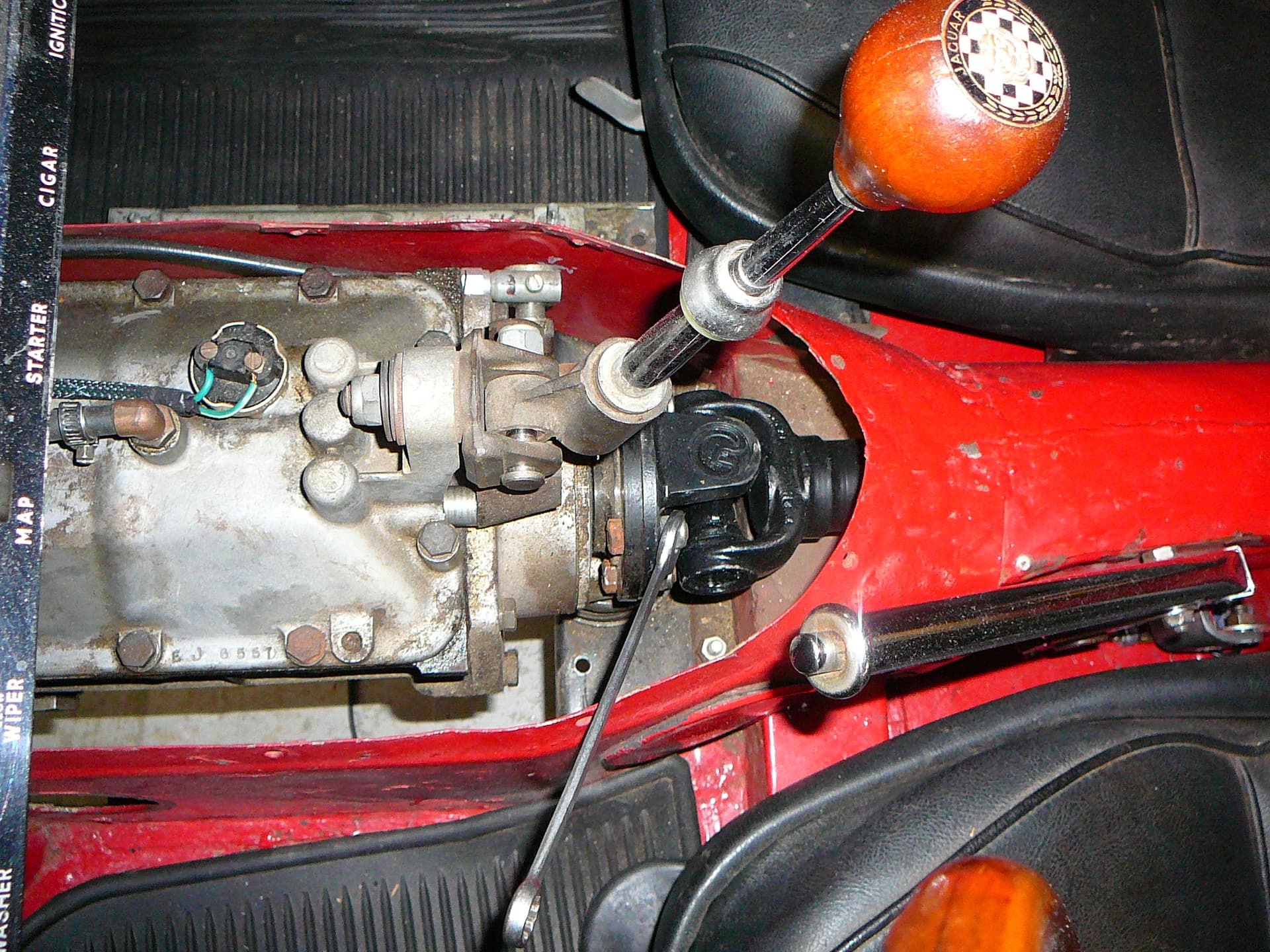
Note my gear shifter didn’t have the needed bushings. Another gift from you know who.
I then remove the rear engine stabilizer by unscrewing the top nut and then the bottom horizontal bolt and just took it out. I left the stabilizer brackets in place. Next was the gearbox breather tube and some wires from the gearbox. The speedometer drive has to come out and the cable moved out of the way, but I left that until I dropped the engine/gearbox a bit to easily get to the angle speedometer drive. I guess I didn’t take a picture of that, but you can see it in the immediately above picture.
So far, it has just been work…nothing too special. I replaced that jack stand at the gearbox with a jack so it could roll. At this point the drive train is supported by the front motor mounts and the floor jack at the transmission. Now to get at that Tie Plate. Jack up the front on the wood reinforced cross frame member with another floor jack and place jack stands under the forward A-frame mounting points. Using a ball joint splitter I split the left side upper ball joint and tie rod end and then took out the bolt at the front stabilizer bar. Next the Upper shock mounting bolt was removed. I had a hard time with this for some reason as I just couldn’t find a neutral pressure point on the shock’s bolt. I had a floor jack under the hub and I tied a rope so the lower A-frame assembly would not fall once the upper A-Arm was free. Eventually it came loose like all things do.
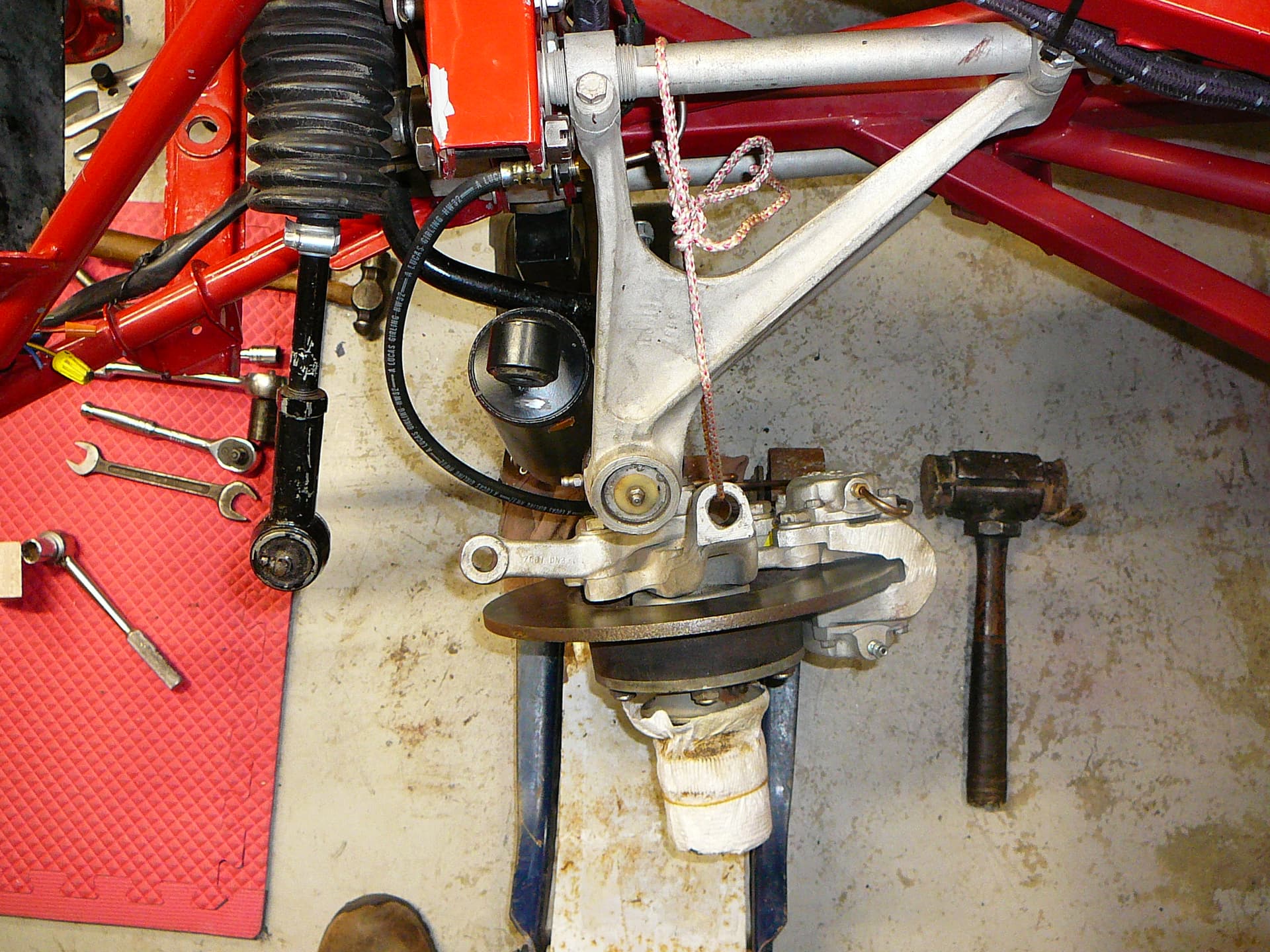

With the left side lower A-frame in full droop, the upper to lower shock mounts measured 18 1/4" and this was sufficient to easily remove the Tie Bolts. So far it has been a pretty easy process and I moved on to the right side expecting the same. Using the same process on the right side, I supported the hub on a floor jack (I had a bottle jack also ready to help just under the lower ball joint as the floor jack on the hub caused the hub to tip inwards at the top). I tied the lower mount with a rope, removed the upper ball joint, the tie rod end, the anti-roll bard link bolt and then the upper shock mount bolt. On this side, that went smoothly. But when I let the lower A-frame assembly lower to full droop, the bolts at the torsion bar brackets were still under tension. Hmmmm. Back to the left side. Well with the large bolt to the frame removed, the two smaller bolts slid right out with a bit of jiggling of the A-frame assembly. With the large frame bolt removed from the right side however, the two smaller bolts were not released. The right side shock mount-to-mount distance was persuaded to go to 18 3/4" by leaning on it…that is greater than the left side and it was going in the right direction.


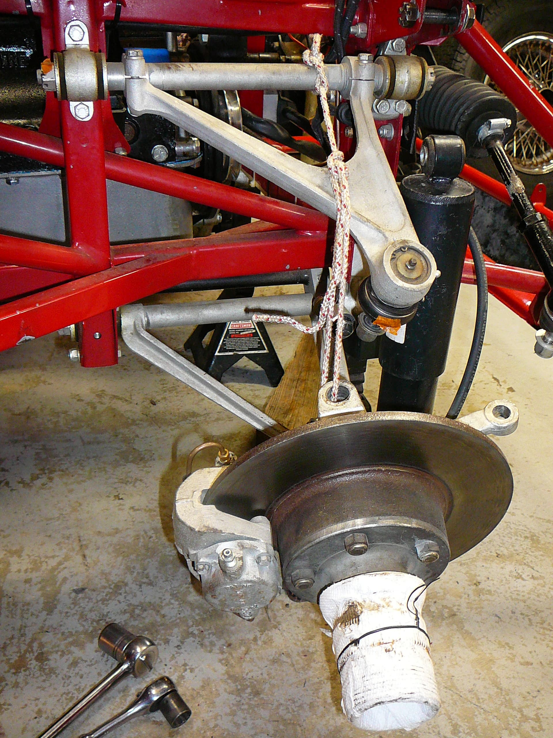

So, time to get innovative. The problem was the tear drop bracket was still applying torsional force to the bolts. I thought something might be bent or the lower A-Arm was interfering with something. Nope, that wasn’t it. I noted that a 16" 2X4 could be used to rotate the lower A-Arm and the bolts could be jiggled in their holes. But I couldn’t do that and reach the bolts. So, I got a longer 2X4 and called for my Better Half. She stood on the 2X4 while I removed the bolts with my fingers. I haven’t yet figured out why there was tension in the torsion bar on the right side when there should have been any. But I did find that the two smaller bolts were slightly bent thus harder to come out of there holes. The extra rotation needed to free the two bolts was only about 1/16", but I didn’t want to strip the threads. Anyway, the bolts are out of both sides and the Tie Plate should come out.


Sure the tie plate would now come out, I tapped it rearwards. What the Hey! It won’t go but a tiny bit towards the rear. There was an answer. The car came to me without any triangular braces between the engine and the bell housing. Right?!! I got a pair but they came from a sedan…that had no cut-out like the E-type. So I cut them to just barely fit them, not realizing the tie plate needed clearance at the triangular bracket in order to move rearwards and drop out. I had left a bit too much flange at the rear of the bracket such that it almost touched the Tie Plate. So, not for anyone else, but for me I had to remove these brackets and modify them so when re-installed, the Tie Plate would fit.


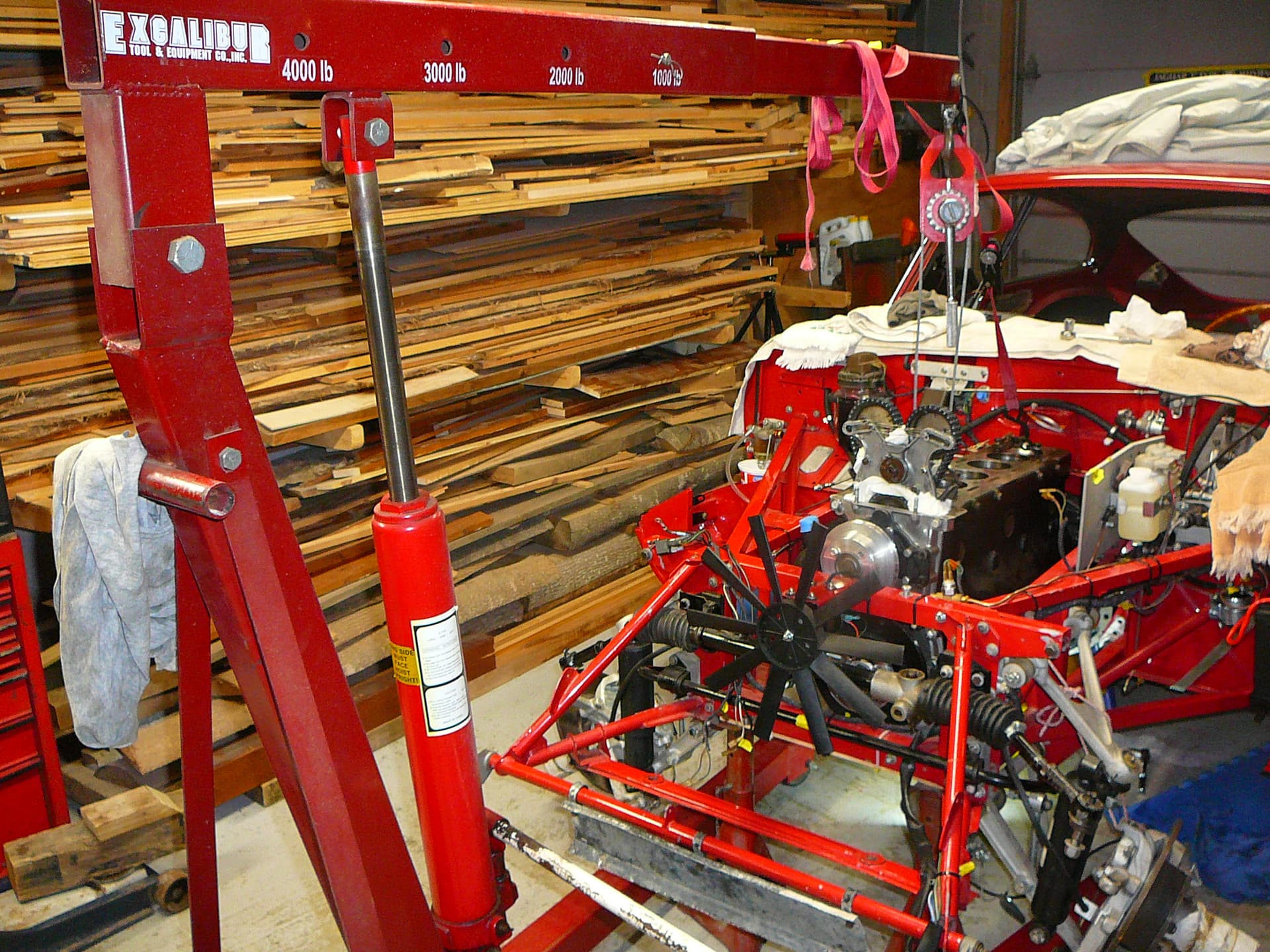
Moving on! I used 4 7/16 X 20 tpi bolts in place of the head studs to fasten the Oberg Tilt Lift to two of the bolts and put a chain between the other two bolts located between Cylinders 1 and 2; this was so I could attached a ratchet strap to easily adjust the angle of the engine/gearbox. Then I removed the two bolts from the front motor mounts and lifted the engine slightly and removed the water pump pulley and then left the engine slightly lifted to drain the gearbox.


And removed the Tie Plate with the two Triangular brackets out of the way

This is even becoming fun. For the last bit of dropping the engine out, I had a friend come over. He could watch for things hanging up but mostly to help with setting the whole rig in the truck. My old creeper with two 2X4 for strength was set under the engine and trany. We just lifted/rotated the engine a bit to get it off the rear floor jack and then lowered it to a point where the speedo drive could be removed.

I don’t know if it would have entailed more drama coming out the top, but dropping the engine and lifting the car was truly easy. We just lowered the engine onto the creeper; it was long enough to hold the gearbox also. It felt stable enough on the creeper that we were confident we could move it easily. Then we removed the cherry picker from the engine and made a rope bridle looped over the picture frame ends at the shocks, and hooked the cherry picker to the bridle. And lifted

the car…as simple as that. Then we just rolled the creeper out from under the car. And then strapped it to the creeped. It rolled really easily.


Here’s a pic of the car lifted in the front without the engine .


Our plan was to put an additional heavy duty strap around the whole drivetrain, creeper and all, and lift it into the back of my pickup. We strapped it down in all directions and parked it in the garage for the night. It’d be heading to Atlanta in the morning.


In summary, once you get all the “stuff” out of the way, this is a straight forward process. One person could do it, in fact, I mostly did. With the engine on a creeper or furniture dolly, it is already on the ground. Pulling it out the top would have taken longer and probably have more risk to the frame.
If I have to do this again though, I would use the Pin the Torsion Bar Brackets method. That way the car is movable and I think pining it, although scary, is simpler than dismantling the front suspension. Here’s a thread on that process. Sucks, I lost that thread now. I’ll find it and edit it in here.
Two threads about pinning the torsion bars, one is a video.
