Dears,
working on fuel sender,
Which is original straight or bent ?
Now try to open and check resistence .
Dears,
working on fuel sender,
Which is original straight or bent ?
Now try to open and check resistence .
Not sure (mine seem different) but if you connect the two wires together, the gauge should peg. You can open the sender and put it back together no problem.
David
Fred, David,
I believe that Jaguar made changes to the internal structure of the fuel tanks between the Series I cars (Fred) and Series III cars (David). So the fuel quantity sender rods probably have different shapes. So someone who knows about the Series I cars will have to look at Fred’s pictures regarding what should be in the Series I cars.
Paul
Oh. I forgot that he does not have a S3. A parts catalogue will be better help, but I‘m sure the Senders themselves are the same.
Thank you for the head up 
The S3 senders come in via the tail light and lack the long tubes with the angle.
Fred,
they seem to differ dramatically, not just because of the kink in the wire, but also because the wire kinked to the right attaches to the left part of the float, making the float protrude far, while the straight wire attaches to the right side of the float and keeps the float closer to the pivot level.
Could it be you have got a left hand and a right hand sender unit?
This is what senders in SI cars should look like as per the book:
Good luck
Jochen
75 XJ6L 4.2 auto (UK spec)
Fred,
this is what the SIII senders look like https://www.ebay-kleinanzeigen.de/s-anzeige/jaguar-xj6-xj12-tankgeber/1261219701-223-404
Good luck
Jochen
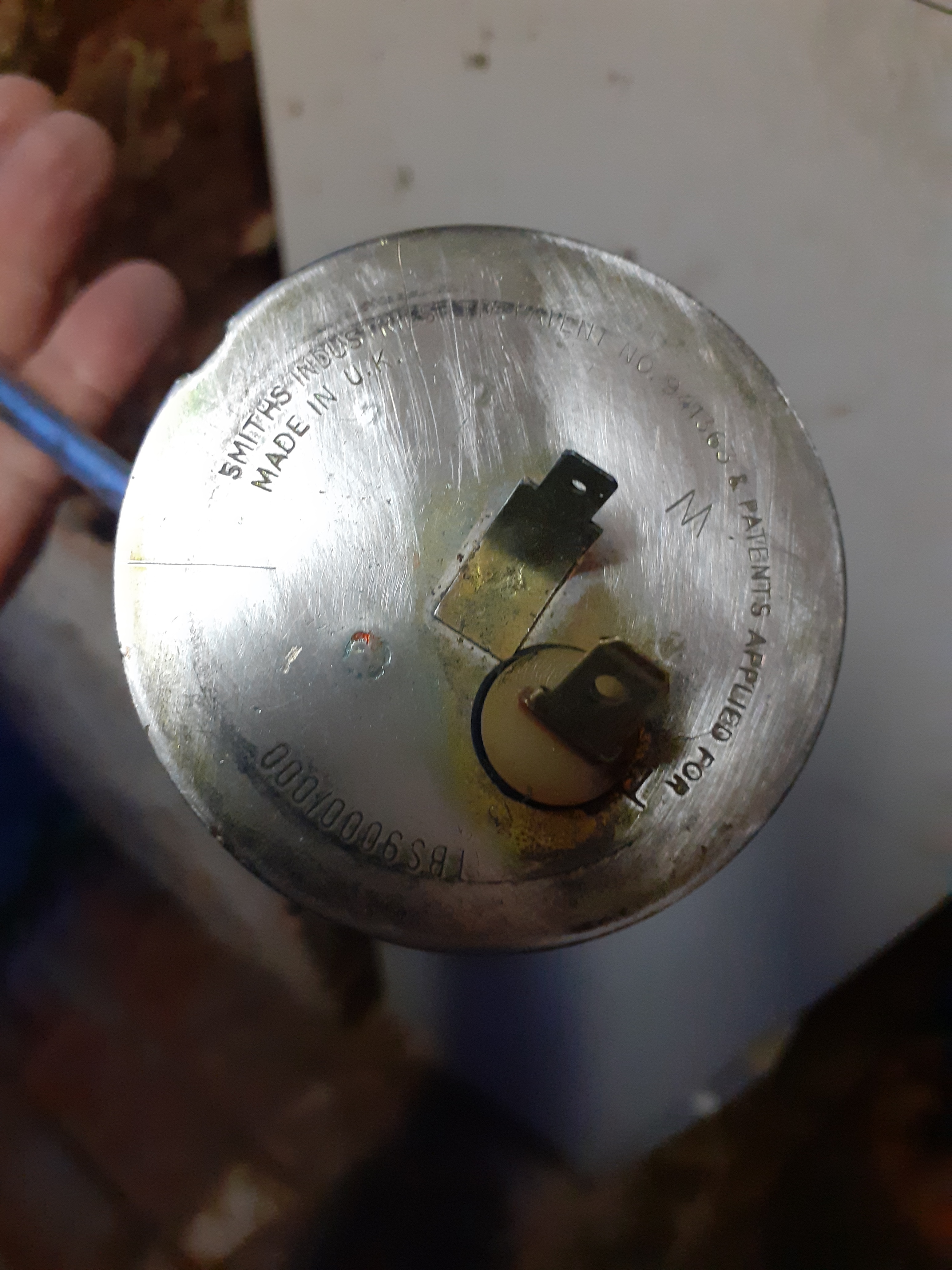
Yesterday ,
cleaned , found that are Smiths made.
Perhaps are coming from '69…(12.9 perhaps date…)
they work between about 20 to 200 ohm.
however
left side no signal to dashboard.
right side give an incomplete reading signal more than zero and stop 1/6 before Full,
Have you idea on additional testing/wash/deoxidation ?
thank 'you
Yes as I said, connect the signal wire to ground and see if the gauge pegs.
If not it is in the wires, switch, gauge.
**
If the resistance between the two connectors varies smoothly between 20 and 200 ohms, Fred - the resistance units are OK…
But the readings also depends on the position of the floats - which normally varies smoothly with fuel level. If the float lever hangs up or the float leaks - readings will be wrong.
Also, the standard adjustment to get the readings right, is to bend the lever - but with the wrong kinks, or incorrect mounting, the levers may snag inside the tank…
Power is fed to the gauge, then gauge ground is switched between the tank units by a separate function on the changeover switch…
Out of the tanks, with the wires connected; you can verify gauge variations by manipulating the levers. The gauge should vary with lever movement between empty and full - and, of course, as David says; shorting to ground should peak the gauge.
All indicating that the connections are OK, and the fault is within the tanks. Which is difficult to test…![]()
Frank
xj6 85 Sov Europe (UK/NZ)
**
Very interesting devices.
Smith made. Aye, and a look at the guage will probably also indicate the maker as Smith.
They are rheostats. or also termed as variable resistors. reduce voltage. changes reflected in the reading of the guage…
Swept by thew arm to change the resistance value. Guage reponds somewhere between E and F. empty or full…
You can read via an ohmmeter or merely a light. as to the latter, bright to dim…
Tale: A couple of years ago, my daughter borrowed my Jeep while I “fixed” her VW Passat. My usually very reliable even if old, quit on her. she called and after some travail I got my road service to flat bed her here.
Initial diagnosis failed fuel pump. The fix called for the tank to be emptied. it is suspended at the rear of the SUV. No luk by any “method”. so, son tackled it anyway with a means of support for the expected weight. The guage showed about 1/4. About 4 gallons or so?? No, it was not heavy!!!
It uses a module, combining the guage sensor and pump submerged in the tank from atop.
In with the new module. Added a few gallons of fuel. On with the key a minute or so before cranking. to charge the EFI. fired almost immediately as it usually does.
Necropsy. Pump part functions in the old unit, the guage not so. The wire coil just worn away in a spot. No more continuity.
The guage lied. just ran out of gas and she did not realize it… Not used to the far thirstier Jeep!!
Diagnosis begins with understanding the function and how that takes place.
Carl
Carl!!! 
Dears, Yesterday worked on chassis wings , some millimeters give a perfect reading empty and full…reostats can accept more fluctation from floatings.
2 sender are ok tested on right line, however left line give no signal ,with 2 contacts closed also…
Perhaps switch doesn’t work during left position???
Next day will try…
Thank ’ you.
Possible! Apparently the switch is often the culprit. Good luck!
**
To clarify, Fred; on prong on the unit connects to the gauge via the switch - the other prong connects to a good ground.
With no ground, the gauge will not react even if the two prongs are connected together…
Frank
xj6 85 Sov Europe (UK/NZ)
**
Friends,
senders and switch are ok. Wire is cut!
Circles on red arrows means 2 “Junctions” ? mean wire have 3 segments ? in this case were are located this junctions ?
Thank’you
Don’t have an exact answer but look under the back and side covers of the boot (easy) or under the center console (less easy)…
**
Indeed, Fred - and instead of a break - it might be a corroded connection?
Which doesn’t make any difference to the location problem…![]()
While the diagram shows ‘single wire’ junctions, they may actually be on multiconnectors - part of loom connections. On the S3; one connector is at the left rear corner, one at the inner fender front left in boot. And one under the centre console. Likely similar on other versions…?
In any case with multiconnectors; wire colours identify the appropriate wires, of course. Which can then be tested for power…
Frank
xj6 85 Sov Europe (UK/NZ)
**
I have repaired a large number of senders when they have gone open circuit, simply by soldering a tiny section of copper wire from (open) coil to terminal
a member of wrote to me years ago, he was pretty excited that my method worked on his failed Lamborghini sender, presumably they are EXPENSIVE