My situation as follows…On my forth ECU and injections still not operating…replaced lead from electric amp to current ECU I believe pin #18…still dead. Can I jump out the ignition injectors manually even to allow a short run. Almost 29lbs fuel pressure at fuel rail. I just want it running to get it out of my garage under power. In the past the line from ignition amp. had a complete ground on way to ECU, they say the section in the engine compartment got so hot and melted the innards of the wire. That is why I ran a new replacement wire. Each time I sent a ECU to Fla. (Module Experts) the results internal dead and not available any more. This is getting old.
Thanks, Ivan (Sloth)
Am I understanding correctly that you fried four ECUs…?
The ECU just grounds the injectors, so maybe you have a short somewhere in the injectors harness or elsewhere and the ECU gets a high voltage the whrong way in?
I would first check with a multimeter that each pin on the ECU’s plug has the correct voltage/ground path/resistance.
You can find all the schematics, plus much more information, at the AJ6 engineering website.
It is quite bizarre though, these ECUs are normally quite robust (even though mine gave up the ghost once), and as well, all these electronic devices usually have some reverse polarity protection scheme built in.
Aristides
Yes, too many ECUs getting fried.
Only safe way to get the car out of the garage is have a friend pull it out with his car.
Not sure what car or year you have, but assume an HE 5.3L V12.
Assume you have a fault in the injector wiring.
Because the ECU has transistors to drive ( earth ) the low side of the injectors the ECU can be fried if any of those connections short to +12V.
Most other connections to the ECU should not cause it to be fried by a wiring fault.
The exception would be any pin that connects to a relay coil such as pin 17.
That pin probably has a transistor to turn on that coil, you don’t want a short on that.
You need a circuit diagram of the injector wiring.
-
One side of all injectors has a KB wire, which is at +12V with ignition on.
That wire comes from a relay, see if you can detach wire from relay.
With ignition off, and ECU connector pulled off the ECU: -
Connect +12V from battery to KB wire.
-
Earth direct injector pins such as 13, 32 etc.
That should cause a click on injectors.
The injectors are not designed for a constant 12V across them, keep it brief.
Check all 4 groups. -
Earth the pins that are from the injectors via the resistor pack, such as 12 etc.
They will not cause such a loud click. -
The above tests should prove the injector wiring.
-
Just in case you have a short to battery in the injector wiring, do this.
Take the +12V supply off the KB wire.
Check all of the ECU pins that connect to the injectors. None should have any voltage on them. -
There is another possibility.
When the ignition is turned on there are relays which will switch +12V to wires which had no voltage in the previous tests. They could short to the injector wiring.
So turn on the ignition, hope that all relays that might cause a problem are turned on, and try test 6) again.
1 Like
just to get the exact question :
are you trying to get the car moving by switching the injectors manually ? I doubt you’ll manage that as this needs to be in sync with the engine rotation / position
re 4 ECU : you tried 4 ECUs and none manages to run the car, or you fried all 4 ?
are you sure the injectors work ? ie are not sticking because of old fuel residues
One other thought here - certainly a possible way to kill ECUs - is if the resistor pack is fried and open circuit, and the ECU is TRYING to drive the injectors open via the initial ON circuit rather than the HOLD circuit that goes through the resistors to limit current. The Peak/Hold - peak ON -high current circuit cannot sustain injectors open at really anything more than idle pulse widths. - just a maybe
That’s def way way to many ECUs fried.
Another thing to note, is that the ECU should fire the injectors for a SINGLE pulse on an un-started car with key on when the throttle is moved to WOT (assuming the WOT switch is working).
Another thing- I’m guessing this is a LUCAS car which would have used either the 6CU or 16CU. It’s worth noting that the 16CU MUST be a Lucas version, because the Marelli version expects a gentle square wave on pin 18 from the Marelli ECU, and from the AJ6 website somewhere, often wont’ tolerate the Lucas spiky signal from the negative side of the coil when the power is cut. I think there might be a zener diode protection diode involved there as well - (it’s noted at AJ6 somewhere.)
What year car? (for confirmation).
I think I’m understanding from the post that the shield for the white wire from the amp to ECU is continuous with ground? Not an open circuit? What kind of replacement wire did you run? It does need to be a coax sort of cable with a shield that gets grounded in the trunk.
I agree the safe thing at this point is to check the pinout for expected values at the harness connector.
~Paul K.
1 Like
Hi Paul:
Thanks for your info on my injectors. That coax lead (white) I replaced had a direct ground with central wire, they say high heat in engine often destroys them. My replacement wire was not coax, I only wanted to use it briefly to get engine running.
Currently, I get voltage to almost entire line of connections from #18 down to around #10. still no igniters opening.
My '89 XJS is not Marelli serial number below 150-----. Let me know where to find the resistor-pack. Thanks Ivan
The resistor pack is over in the front/right corner of the engine compartment. It is worth removing the plug, cleaning the contacts, and putting back. Corrosion there could happen.

1 Like
Well lets go through some possible tests with the ECU out.
There are a number of inputs to the ECU which just are not critical for the car to start and run. W/o those inputs the ECU just doesn’t make as finely calibrated of decisions and kind of limps around the inputs it has. Really it comes down to two critical electrical one ones and one analog one: The Coolant Temp Sensor input, the Engine Speed Pulse input from the Amp, and the Vacuum input (MAP sensor).
The O2 sensors can make a MPG difference, but the car will run ok with them unplugged, - same for the Air Temp Sensor, Throttle Pot (it’ll be sluggish), and Full Load signal.
In 1989 they added a relay upstream of the main relay called the EFI Main Relay (eliminated later). It’s in the dash. With Key-On - that thing energizes as long as the inertia switch says the car is right-side up. That provides power to energies the main relay, which we know is working ONLY because you have fuel pressure, and the Fuel Pump Relay (FPR) is dependent on power from the Main Relay, and command by the EFI ECU which grounds it in order to run the pump. With Key-On the ECU will turn the FPR on for 5-15 seconds to prime the system and get it up to pressure. Since you have fuel pressure, we know that is occurring and thus the ECU has power.
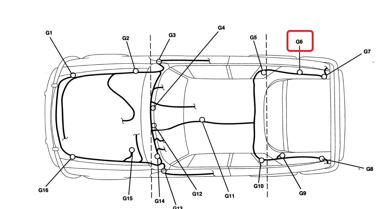
The ECU’s power comes from the main relay and provides +12V on pin 22 (clearly it’s there because the ECU couldn’t command the FPR without it) and completes the ECU powering circuit ground G6 on pin1 of the ECU (worth testing for continuity to ground, but I’d expect its there.).
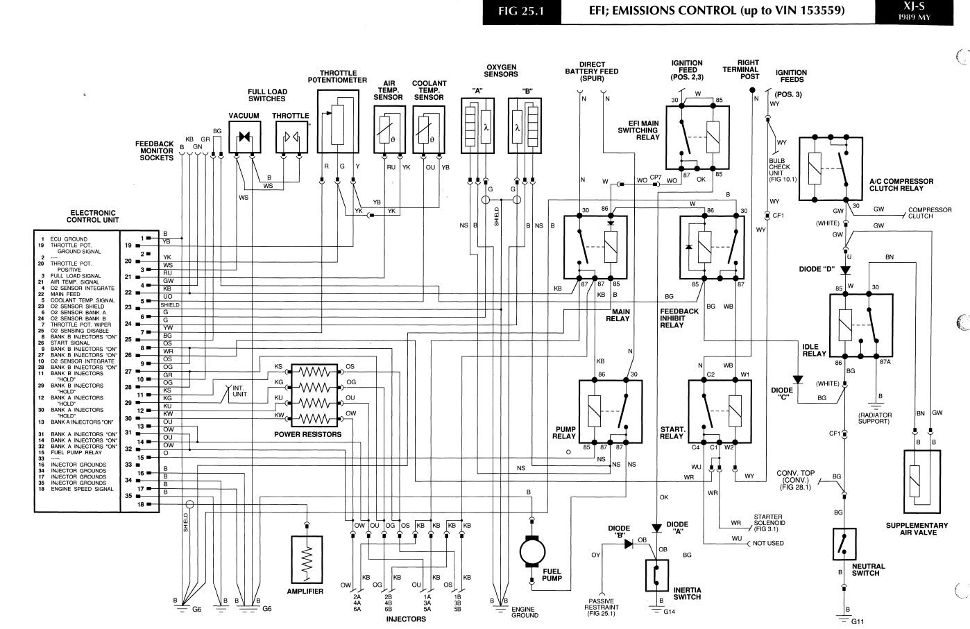
What happens next occurs when you try to start the car. Ing power tries to engage the starter relay as long as power can get through the Feedback Inhibit Relay (FIR) (not used on every year car) on it’s way to ground G6 in the trunk (G6 is a VERY important ground). The FIRelay will be energized as long as it’s happy with the Neutral Safety Switch. IF all that’s good, the engine will turn over due to an energized Start Relay saying YES to the start solenoid.
When the start relay is energized +12V from it ALSO flows to pin 25 of the ECU which by the documents is ALSO supposed to help the ECU know to run the fuel pump along with running input on pin 18 - post key-on pressure-up.
The car is now cranking. It will have SPARK - IF the Lucas inductive pickup is producing a basically triangle wave from the 12point star wheel in the distributor. That provides the signal pulses to one end of the GM Amplifier inside the Lucas AB14 box. On the opposite side of the amp is a +12V on one of the pins (same as to the coils) and a negative side dwell control that is closed circuit to charge the coils and opens to collapse the field and fire them. THAT side is split 3 ways (with a few resistors in between). One to the coil. One to the Tach, and the terribly important one to pin 18 of the ECU to let the ECU figure out engine speed.
IF the ECU is getting that signal (which is supposed to be shielded to GROUND G6), it should try to start firing the injectors. Technically those injectors are grouped into 4 groups of 3 as if the ECU had 4 outputs, but that’s not really the whole story (they’re fused internally so it’s really 2 groups of 6).
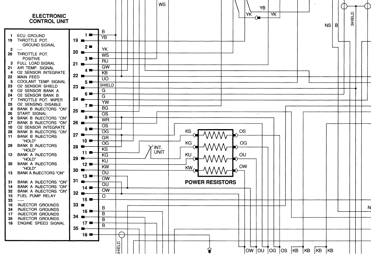
Starting on A bank:
Harness side Pins 13 & 14 AND 31 & 32 are the High Amp Load brief injector-on pathways to provide a ground for the A bank injectors to get them open
- A Bank Injectors “ON”
- A Bank Injectors “ON”
.
- A Bank Injectors “ON”
- A Bank Injectors “ON”
You should observe continuity between 13 & 14, as well as 31 & 32. Also +12V (about) should be measured on those pins with key on as power flowing through those injectors waiting to be grounded by the ECU.
The same for B bank injectors on pins 8&9 and 27&28
- B Bank Injectors “ON”
- B Bank Injectors “ON”
.
- B Bank Injectors “ON”
- B Bank Injectors “ON”
Once the injectors are OPENED, the current would get too high for the ECU to sustain it, so the ground pathway is switched over to different pins going through the Power Resistors.
For A bank that’s Pin 12, and Pin 30 (not continuous to each other harness side - but possibly fused internally inside the ECU).
-
A Bank Injectors “HOLD”
-
A Bank Injectors “HOLD”
Now the interesting thing is that pin 12 is continuous via a loop to 13/14 BUT you’d measure the resistor pack’s resistance between 12 & 13or14.
The same for pin 30’s relationship with pin 31/32.
B bank is of course the same:
-
B Bank Injectors “HOLD”
-
B Bank Injectors “HOLD” (Pin 29) There’s something about the forum’s software that’s forcing 29 to look like 12 because of #11 above and it’s trying to make this an ordered list. So just scratch out 12 and make it 29… which is oddly there when I go to edit this post).
With 11 having a resistance value measured across 8/9 and pin 29 the same across pins 27/28
Resistances should all be equal unless there’s a problem with the resistor pack or wiring. Off hand I can’t remember what the Ohm values should be.
Lastly, where does ALL THAT power from the injectors go? It’s dumped to GROUND G6 via ECU pins 16, 17, 18, 34, and 35. (in what order/relationship I’m unsure… just know that that ground is important.) It becomes worth checking Ground G6 to see if it’s clean and can handle the full load of power being dumped to it via the ECU and other sources.
Additional checks:
Resistance wise, you should see a clean sweep to around 4KOhm on the throttle pot from pins 7 to either pin 20 or 19. Normally the ECU would impart a voltage across the Throttle Pot to measure the voltage change as the TPS sweeps over it’s range.
On pin 3 do you get continuity to ground when the throttle is WOT? (I.e. is the throttle micro-switch working at WOT).
Do you get the critical resistance values from the Coolant Temp Sensor across pin 5 and 19? (Usually the car will un-startably massively over-fuel w/ bad or no input here).
I think you can discount testing the O2 sensors and Air Temp Sensor for the time being. They’ve got nothing to do with your starting problem.
~Paul K.
3 Likes
yes, speaking of G6 ground, just as a precaution within the first week I got my XJS, I removed the grounding wires that all attach to body over next to battery, sanded down all connectors and the actual body where the bolts screw into, and cleaned up the bolts/screws and holes. Ground is super important here.
1 Like
Ha, ground connections. In the first week of owning my Alfa I had to track down an electrical problem. Everything relied on “a close(ish) bit of bodywork” being grounded, hardly any actual earth returns via a cable. But that bit of bodywork may be attached to a bracket, attached to the bumper, attached to another bit of bumper, attached to another bracket, attached to… gawd knows where. In the end I rewired the car with proper earth connections. And relays. The headlamps were being run directly through the (super expensive to replace) column stalk switch. That got fixed as well.
Fabulous car design, engine, gearbox, brakes etc, but It seemed like the Alfa engineers had all gone for a very generous lunch, and then left the janitor to sketch out the electrics on the back of a cigarette packet.


Hi Paul: Thank you for the very detailed letter and working plans…I fully intend to follow your explanations until I solve this no-start situation.
I have poured so much money in this auto but still 'am challenged by solving my problem.
Once again thanks for the data and I will keep you in the loop when solved.
Regards,
Ivan (sloth)
1 Like
Attn: Paul:
Thank you for your help…I followed your details and I think I see some daylight here…
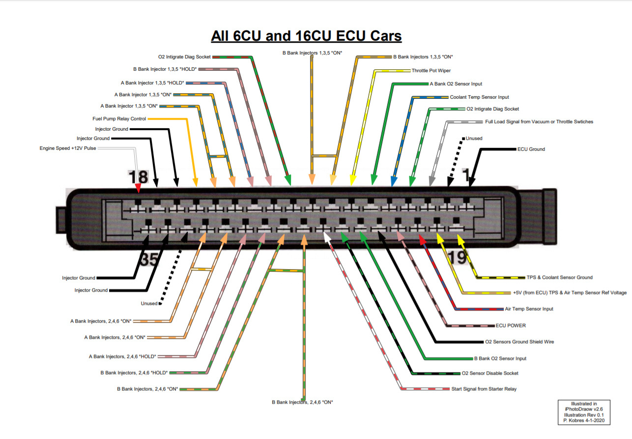
Using your photo of the ECU pin data…here’s is what I find… All pins that pertain to ignitors show power with key on… I did find that pin segment #19 does not show ground it’s hard to read some sort of TPS sensor. Would that keep my engine from firing. (Please advise)
Thanks, Again Ivan (Sloth)
Depends…how many volts do you read on your TPS with ignition on?
Ok Greg:
First I admit I cannot find the TPSensor.but most voltage after the spark magnifier is around 24volts.
Of course before it’s just under 12 volts. I went through very carefully the voltage from the ECU plug and I get voltage to all the leads for the igniters . The terminal #19 shows no ground to the TPS…
It’s possible a plug may have severed or something…
Thanks, Ivan (Sloth)
First an edit to my March 9 post above:
Where I said: " GROUND G6 via ECU pins 16, 17, 18, 34, and 35" This is slightly incorrect. #18 is the RPM/ speed input from the ignition. Sorry about that. It should read "pins 1, 16, 17, 34, & 35).
Its good that you have voltage at all the injector lead pins with key-on. That is what we’d expect.
Re pin 19 to the TPS, there may be a malfunction there but it should not matter for the purposes of starting and running the engine. The car will start and run fine without the TPS plugged in. The critical input is the temp sensor, but because the CTS and the TPS share the same ground, it could still mean the ECU cannot read the CTS (coolant temp sensor) values and that indeed would cause a problem starting. I’m not sure it would cause the injectors to fail entirely but this is worth investigation.
Lets double check this:
Unplug both the battery and the ECU (important). Put a jumper wire across the B bank CTS sensor connector:

Using the diagram from the other thread (Fuel Injectors Sleeping - #9 by V12JagGuy) put your multi-meter in continuity mode and check for an audible Beep when probing pins 19 and 5. The loop you made by jumpering the connector should tell you if the wiring is good or not. If you get no beep/no continuity then yes… there is a wiring problem… and it usually is right there at the temp sensor connector itself… but yes… it could be where the #19 Yellow/Black wire connects to the TPS plug itself for the TPS shared ground on pin #19.
I have forgotten. Have we established if the injectors will fire a SINGLE burst with key-on if the throttle capstan is rotated to wide open throttle causing the WOT switch to close? (If it does, it tells us for sure that the injector wiring that you’ve checked IS working, and that the ECU is capable of firing the injectors)… which would point even more strongly to a broken connection to the temp sensor.
~Paul K.
Hi Paul:
Well, I did the following: Jump out CTS nodule no continuity to point #19 or #5…(I repeated test three times)
Checked for continuity on CTS unit still in block (no continuity) open circuit …I am guessing but is it possible the unit in block should show pins inside closed and open when warm?
Now back to wiring plug has tag labeled water (looks factory) but lead has black wire wrap that looks lilke amature wrap. So in conclusion , wire on plug looks like a break somewhere but goes into large fat cable in rear of engine. I could sever plug and run two new leads to ECU. Please advise.
Once again thanks for your time and patience…
Sloth
Well for sure the ECU isn’t able to read the Coolant Temp Sensor and that’s likely the problem.
Check the wiring for a break AT the Temp Sensor connector and fix that if it exist before going through all the diagnostic below:
IF the test had worked, you’d have read continuity (0 Ohms) with the jumper in the connector. If you had read the coolant temp sensor (CTS) cold (with it plugged in), you’d have gotten around 2.2K Ohms… when hot (up to temp) it reads 260 Ohms (there about). The ECU actually applies a 5V signal across those leads/terminal and reads the voltage drop to figure out temp. For our purposes reading Ohms tells us if it is working. IN this case, it is an open circuit… so one of the two wires to the CTS is broken.
The next check is to do the same test but across pins #19 and #20 of the Throttle Position Sensor (TPS) connector under the bell-crank (but put your meter in Ohms mode… range 0 to 5K Ohms (might be 0 to 20K Ohms on the meter). I believe the reading you’re going to get is around 4.5KOhms to 5KOhms … IF… IF wiring is good to the throttle position sensor (TPS). (That’s because the wiper probe - red in the diagram should read close to zero ohms to about 4.5KOhms in operation as the throttle opens and closes) [The full resistor is represented in blue box in the TPS] … again the ECU uses voltage to check this, but we can test with Ohms (Green to Yellow wires across the entirety of the internal resistor corresponding to pins 19 and 20).

The thought here is to maybe narrow down WHERE your wiring break is. It’s probably in the engine bay… and I still say check the end connector AT the temp sensor very carefully as that’s where it most likely exist.
IF you get no reading (looking for about 5KOhms), try unplugging the connector at the Throttle Pot and putting a jumper across the harness-side plug where the Green and Yellow wires plugged. That should make a loop across pins 19 and 20 with zero ohms. IF you get NO continuity… then it could be a break in either the wire for 19 or 20, BUT it becomes likely that it’s in #19… that pesky Yellow/Black ground wire… and PROBABLY where the wire spices at or near the TPS connector to ALSO serve as the ground wire out to the CTS.
The other thing is we’re not sure if your wire break is in the Yellow/Black wire, OR the Orange/Blue wire for the CTS IF the test above WORKS. Next we narrow that down.
IF you get continuity (or 5KOhms) between 19 and 20 with that loop (or plugged in) then the break is either in the short Yellow/Black ground section of Yellow/Black between the TPS and CTS, OR in the Orange/Blue wire. Next that needs to be narrowed down. We need a known working loop for that and we can re-purpose some wires to ensure we have that loop available.
Change your throttle position jumper to be across the Green/Red plugs (i.e. harness side Yellow/White and Yellow/Pink wires) Now check continuity across pins 20 and 7. I’m expecting/hoping that works well at 0 Ohms for the next test. If you get good continuity then you have a KNOWN good set of wires to the ECU plug that we can repurpose for a continuity test.
That knowledge lets us differentiate which wire of the CTS has the break (or if both do).
Create a LONGER jumper between the Orange/Blue connector pin at the CTS and run it to either of the two plug spots in the last test… where the red or green from the TPS plugged into either the YW or YK wires of the harness TPS plug. All we’re doing here is using a known good wire path (hopefully) to create another loop to test.
Now you can test continuity across pin #5 at the ECU and either pin #20 or #7 (whichever you chose for the loop) to check for continuity. IF you get continuity then the CTS’s Orange/Blue wire is good. If you don’t then it has a break somewhere – probably in the engine bay… but it may require a lot more looking along the harness.
There IS such a thing as a signal injector for finding out where a wire is broken, but I’ve never tried it for car wiring. (Obviously disconnect the battery and ECU).
")

~Paul K.
.
Hi Paul:
Once again thanks, I cut off the CTS plug and wired in a new plug.(I too have been told the engine compartment and it’s heat usually causes the problem), ran the continuity test (no life at #19,nor #5)
Replaced and soderd the old plug. I now will follow your advice and zero in on the TPS area for breaks.
Your pupil…Sloth
1 Like