Several people have asked me for more explicit instructions on how to do this modification so here you go.
You will need from an Auto electrician shop:
Parts
3 metres PVC 28/.30 17 Amp cable blue/green
1 m PVC 28/.30 17 Amp cable black
1 m PVC 14/.30 8.75 Amp cable black
1 m PVC 14/.30 8.75 Amp cable blue/red
1 m PVC 14/.30 8.75 Amp cable blue/white
1 m PVC 14/.30 8.75 Amp cable red *
1 m PVC 14/.30 8.75 Amp cable red/green *
1 m PVC 14/.30 8.75 Amp cable red/white *
2 x 20 Amp In Line Waterproof Fuseholder (one fuse per headlight for safety)
4 x Standard Blade fuse with built in LED 20 amp (two for spares)
A selection of bullets, sleeve connectors and spades.
2 double contact 12V 30amp SPST Relay
NB: The cables with a * are optional but do allow you to extend the wiring for the indicators/side lights to make a neater job.
The Relay’s:

or:


Pins 85 & 86 - relay coil; switches relay when fed 12v (your existing headlamp power feeds are used to operate these)
Pins 87 & 87A - common contacts, one per headlamp (your existing wiring to the headlamps go here)
Pin 30 - connects 12v direct from battery to 87 & 87A when relay operated - the headlamp circuit (new wire goes here)
Alternatively you could use a pair of fused relay’s to simplify the installation:

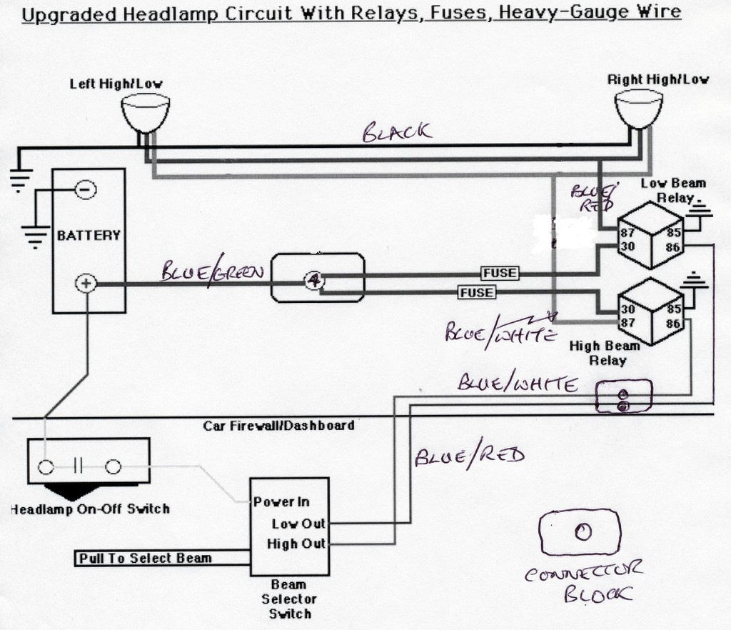
Wiring diagram:
Procedure:
- Disconnect the battery earth
- Remove headlamp cover and sugar scoop from nearside (L/H) of bonnet.
- Attach the two relays to the headlamp diaphragm. You can use at least one existing bolt but you may need to drill a hole for the second relay. Label the relays ‘Main’ and ‘Dip’ for easy identification later.
- Disconnect the following headlamp harness wires from the 10 way connector located on the headlamp diaphragm - blue/white x2, blue/red x2, black x2 and set aside. These are the bundled harnesses which run to the headlights, not the ones from the multi plug/socket - leave the latter connected to the the 10 way.
- Make up two 12" jumper wires each with a bullet on one end and a spade on the other using blue/white and blue/red 8.75amp cable
- Connect the blue/red wire spade to pin 86 on the ‘Dip’ relay
- Connect the blue/white wire spade to pin 86 on the ‘Main’ relay
- Connect the bullet of the blue/white wire to the blue/white on the 10 pin connector
- Connect the bullet of the blue/red wire to the blue/red on the 10 pin connector
- Make up two 12" jumper wires each with a bullet on one end and a spade on the other, both black 8.75amp cable
- Connect a black wire to pin 85 on the ‘Dip’ relay. Connect a black wire to pin 85 on the ‘Main’ relay
- Connect the bullet connector of each black wire to spare earth connectors on the 10 way
- Reconnect battery and test relays. You should hear them click with the headlight switch on and operating the main/dip switch.
- Disconnect battery
- Cut off the bullet connectors on the two blue/white and two blue/red headlamp wires you set aside earlier. Replace with spade connectors
- Connect both blue/white spades to pins 87 and 87a of the ‘Main’ relay
- Connect both blue/red spades to pin 87 and 87a of the ‘Dip’ relay
- On each waterproof fuse holder attached a spade connector to one end and a bullet connector to the other
- Connect the spade end of one fuse holder to pin 30 of the ‘Main’ relay and do the same for pin 30 of the ‘Dip’ relay. It does not matter which goes where as they are going to a common supply
- Connect the bullet end of each fuse-holder to the red/yellow on the 10 way. This is the unused ‘Fog-lamp’ wire and nothing else should be connected to it. Check to make sure the red/yellow goes back to pin 6 on the bulkhead multi socket - someone could have messed with the wiring!
- Make up a 12" jumper wire using black 17amp cable with a bullet on one end and an eyelet on the other
- Remove a bolt from the bonnet area, make sure it is clean and attach the black wire eyelet. Use petroleum jelly or similar to ensure there will be a good stable earth connection. Make sure the bolt is tight.
- Connect an ohm meter between the bullet of the black wire and the battery earth terminal. You should have a reading of no more than 0.4ohms. If it is higher you need to select a better earthing point or remove paint from under the bolt
- Connect the bullet end of the black wire to a double sleeve connector.
- Connect both black wires from the headlamp harness you set aside earlier to the double sleeve connector
That is it for the headlamp bonnet area but leave open for the moment until you are sure everything works. Next the main heavy duty headlamp feed.
- Check the battery earth is still disconnected
- Release the bonnet plug and remove any cable ties to allow you to extend the harness as far as possible outside the engine compartment
- Remove the rubber cover and/or release the socket from its housing.
- Unsolder the red/yellow cable from pin 6 and cut back
- Thread the blue/green 17amp cable down the plastic sleeving of the harness and solder to pin 6
- Reassemble the plug and re-attach to bonnet. Use petroleum jelly on the contacts to ensure low resistance
- Run the blue/green cable alongside the existing harness attached to the near side frame to exit behind the battery adjacent to the live battery terminal.
- Cut the blue/green cable to length and terminate with a suitable size eyelet.
- Connect eyelet to live side battery post. Use petroleum jelly to ensure good contact. Tighten well
- Re-connect battery earth and test o/s headlight (the nearside will not yet be connected) for correct main/dip function. Make sure the nearside headlamp connectors you insulated earlier are not touching anything!
- Test the headlamp wiring by using a voltmeter between black and blue/red (dip); black and blue/white (main). You should see 12v on each when switched.
At this point you can go ahead and replace the sugar scoop, bowl and headlamp although you may now want to consider if the re-wire has left anything under any strain and everything is tidy. This is where those wires I highlighted with a * (above) come in handy - they allow you to extend the side/indicators with jump wires and sleeve connectors. You also want to make sure you can reach the fuses from the bonnet mouth in case they ever blow. Use cable ties to support the wiring and sleeve connectors.
This was my final wiring:

Dedicated earth on right hand side; red, green/red, green/white bundle in centre is the side/indicator extension loom I made up to allow more room; standard 10 way connector on left; I replaced the red/yellow ‘fog lamp’ wire with the blue/green 17amp wire but it is not necessary to do so given the very short length; not shown on this picture but I also added a jump wire between the loom earth on the 10 way and my dedicated earth point; I used ‘piggy back’ connectors on the relay earth’s to reduce wire clutter.
With the L/H headlamp back in place check the operation and beam alignment before replacing the cowl (on an S1). This upgrade will work on both +ve and -ve earth vehicles and applies to all series E-Type’s. Go out and test at night where you will find the dip beams are now as good as the previous main beams and the main beams are as good as a modern vehicle. Total time spent - about 4 hours.
Notes:
a) You can use any colour of wiring you have lying around but it may make fault diagnosis difficult and really confuse a garage or the next owner. For the cost of the cable it is worth sticking to standard colours.
b) Dismantle the 10 way connector (just remove one screw and loosen the other to swing the cover out of the way) if you have the time. The spring connectors can then be removed individually and cleaned to ensure a good contact. Reassemble with lots of petroleum jelly.
c) I chose blue/green for the 17 amp feed because that colour combination in not used anywhere else on the E-Type.
d) If your headlamps are looking a bit dull try washing them in Fairy liquid inside and out. Rinse well in warm water and leave then to dry thoroughly before reinstalling.
e) Only headlamps that will fit the S1 are the Wipacs or Lucas units. For the S2/3 you have the choice of Cibie’s or the Crystal polycarbonate headlamps for even better light
f) For even more light fit a pair of Osram Night Breaker Plus or Philips X-treme Vision + 100% H4 65/55w bulbs. They cost about $30/pair but are very good.
g) I found it was easier to connect up the relays if you left the securing bolts slack to allow access. Don’t forget to tighten them afterwards!
h) Apart from the blue/green wire going to the battery post there is no evidence of the modification. You could tidy that up on the 4.2 cars by connecting the blue/green to the bulkhead terminal post instead.
i) Check the alignment of both headlights - you will be amazed how much better your forward vision will be if this is done correctly:

The instructions may seem daunting but I decided to document each step so anyone can follow the procedure without head scratching. The instructions and wiring apply to both +ve and - ve earth cars. Angus Moss was my instruction guinea pig and he has now done several cars by following the steps, all without problems.
Any questions, just ask.
David