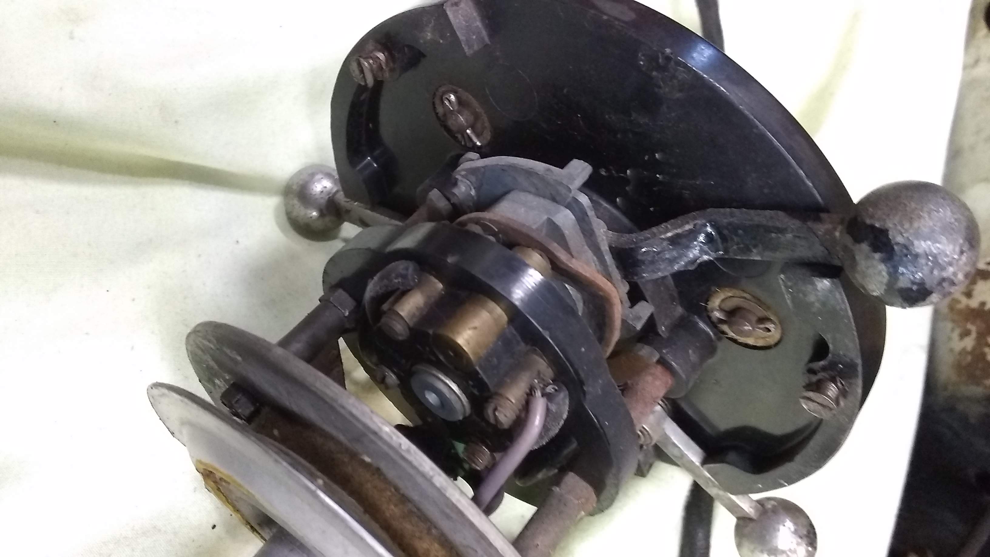
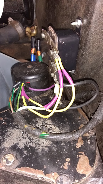
My car has not been on the road since 1960, and I am now examining the manette for the first time. It has 2 knobs hat are marked “dip/head” and “left/right”,… no third knob. There are 7 wires to it which is the correct number, although the colors do not match my wiring diagram.
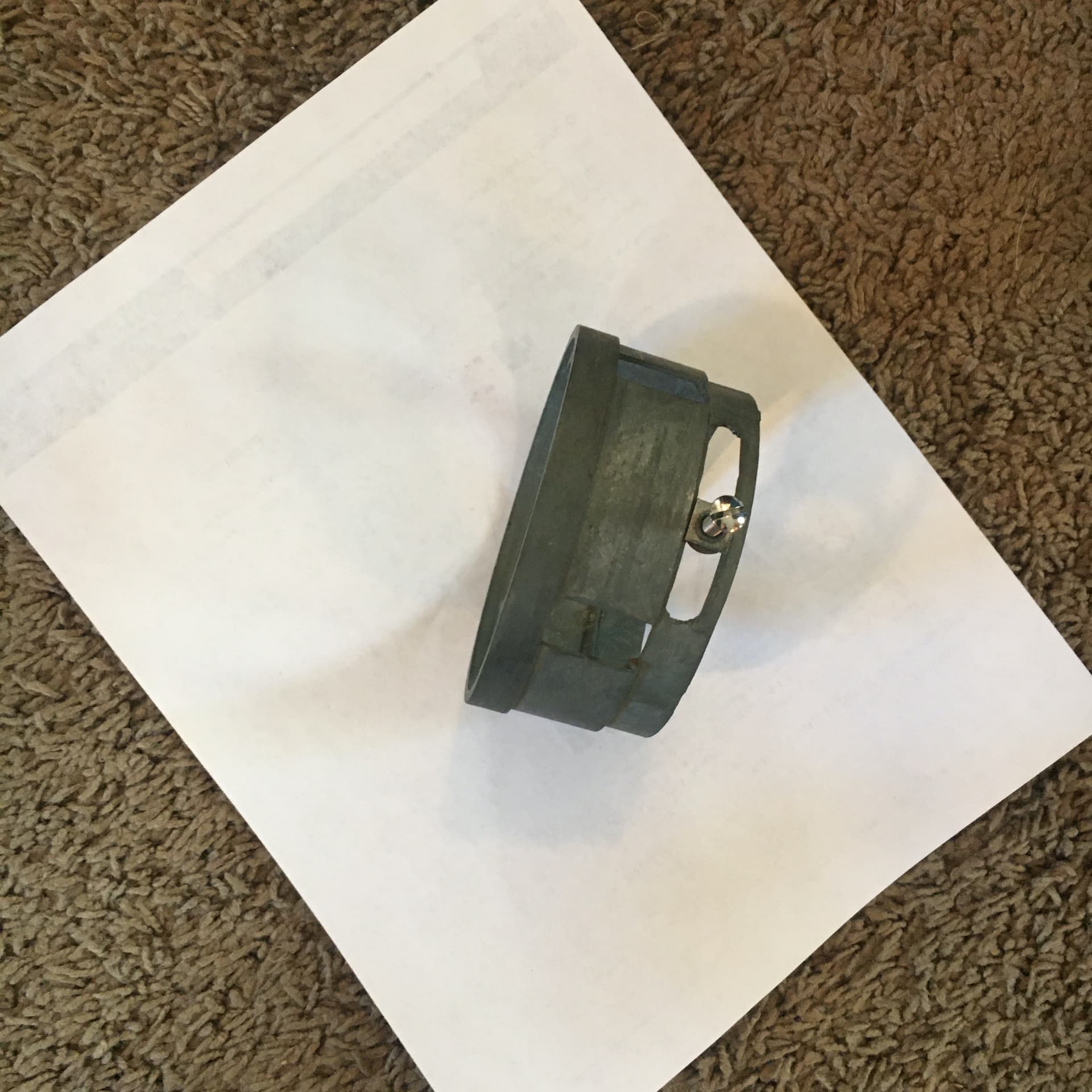
Pictures: On the metal sleeve a large screw is placed so the manette can rotate in a notch. I do not see a benefit. Also, there are 2 stops or bumps
inside this sleeve and I do not see that they hit anything.
I think you do have all the parts. (Assuming your car was not designed to have manual ignition advance/retard.)
The sleeve with the two bumps is made adjustable in case your steering wheel is not aligned accurately with its spokes exactly 12 o-clock, 3, 6, 9 o-clock. Clearly the manette should not rotate with the steering wheel and it is clamped at the foot of the column so that the trafficator switch always has its knob at 12 o-clock except when indicating left or right. The bumps on the sleeve should be adjusted to that they are equidistant from 12 o-clock. With those adjustments made correctly then the trafficator switch should self cancel when the steering wheel returns to straight ahead.
The bumps act on a pair of rather innocuous arms on the switch.
Peter,
Thanks for your response. I see what you mean about the bumps in the sleeve. The arms they hit, only stick out when the turn signal is on. I am encouraged.
Regards,
Dennis
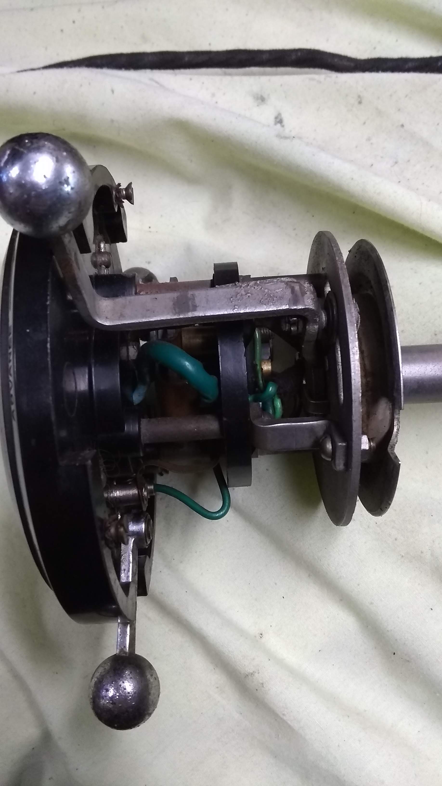
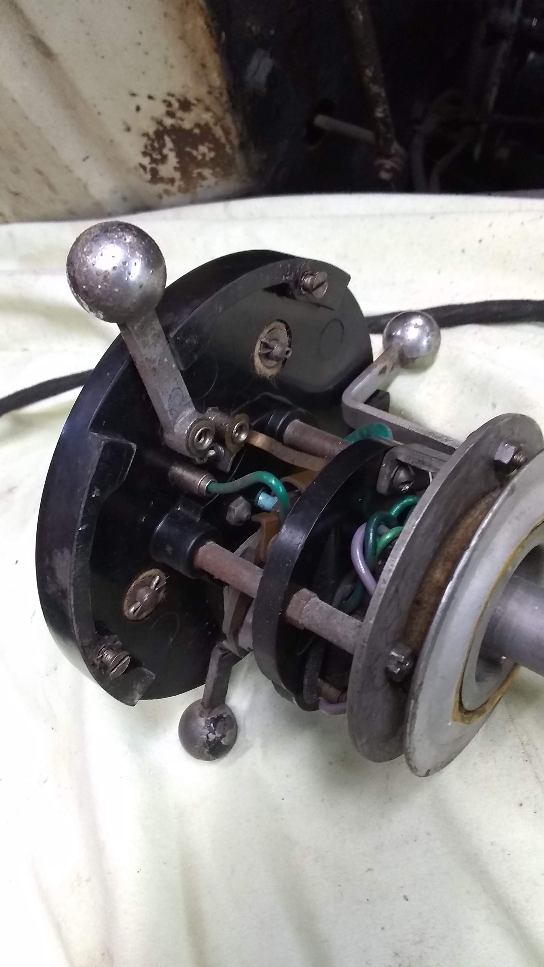
Peter is on the mark here Dennis. I think the manual advance system was superseded early in the production run of the Mk IV, probably '46. If you look at the rear of the manette head as you move the trafficator switch left and right, you should see a little finger (one per side) swing out. This is the self canceling mechanism that engages with the little lugs inside the collar. Clean all hinging points and apply a little oil.
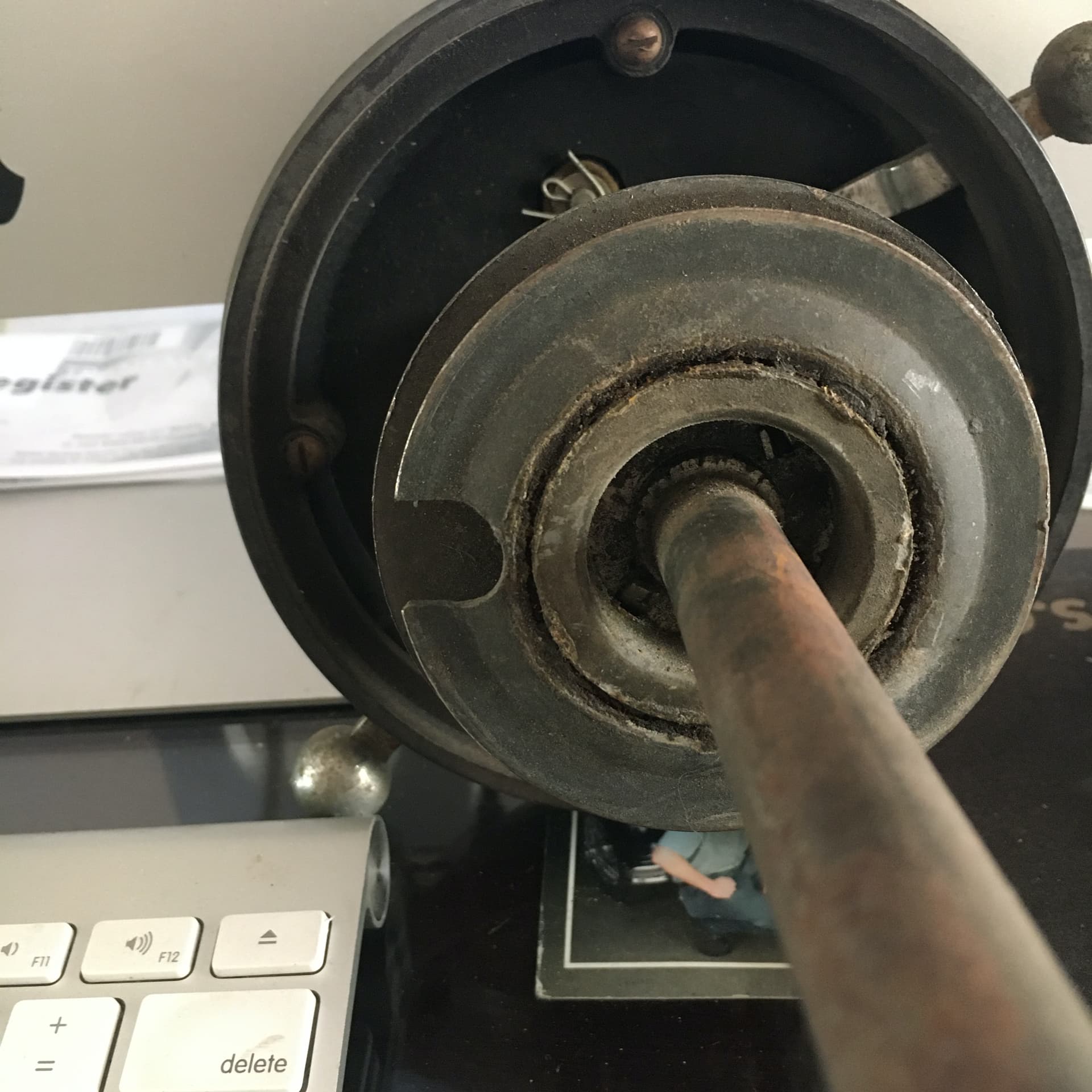
A bit more information - the bottom disc is the ring that locks the whole assembly in the steering wheel hub. It is also a bearing and should be free to turn and to be lightly lubricated. It seats firmly into the bottom shoulder in the hub so this area should be cleaned well. There are two small tapped holes in the side of the hub which are for grub screws with pointed ends. These tips wedge themselves onto the top edge of the locking ring when seated onto the shoulder. I actually made some from standard screws because a p.o. had installed standard screws which bite into the edge of the ring, burring it. These screws, if you don’t have them, have a pointed tip of about 45° and a slotted head which is slightly rounded. The rounding is to give a smooth feel if it projects slightly after tightening.
Check the cleanliness of the contact points of the switches too. These are very basic touch point contacts.
Yes, Peter L. makes some very useful additional points. The cleanliness of the trafficator switch points is particularly important because the initial current to activate the semaphore arms is quite high and relies on really low electrical resistance at the switch points.
Yes, my manette wires also do not match the wiring diagram, although I only have five, apparently because Lucas did not have small gauge multi-colored wire in those days. Same with my Mark V and XK120, small gauge single colors. Five cloth covered wires wouldn’t fit down the tube.
My SS headlight switch had 80 years of dirt in it and was a location of high resistance, which made it get hot, which made the compression spring inside it relax, so the contacts were not being pressed together. I took it apart, cleaned all the contacts, stretched the compression spring back to normal, put it together, and it works fine now.
I have the grub screws, but was unaware that the bottom disc is also a bearing. I am sending a picture to confirm that the petrified piece on my manette is supposed to move.
The manette sat on the back seat of the car from 1960 until I bought the car. I will spend a lot of time cleaning it, also the long wires are wrapped with electrical tape that is now coming loose. I will get some black shrink tube to secure the length of the wires.
When this bearing is sorted out, I hope to see the logic in how the turn signal centers. For now, it all seems to be anchored to the steering wheel.
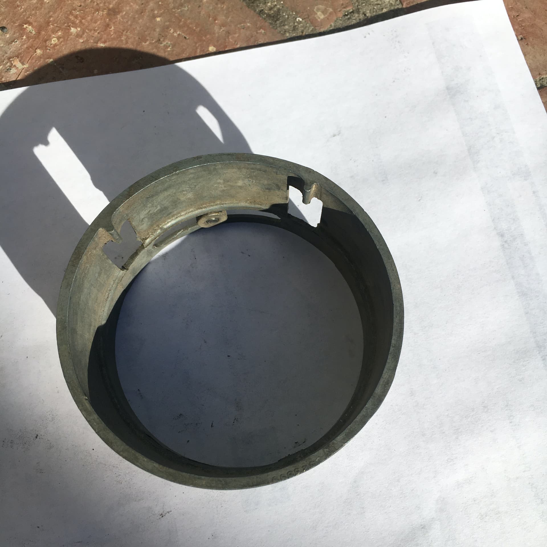
The tube that goes down the column and all the Bakelite parts are static and do not rotate with the steering wheel. The tube with the cancelling bumps and the disc in your photo with the notch out of it are both anchored to the steering wheel and rotate with it.
You will see that the tube containing the wires is not long enough to go to the full length of the column. This tube links into a second tube part way down the column that is clamped at the point where the wires exit to connect to the main wiring loom.
I can’t remember which tube has the larger diameter (I think it’s the one shown in your photo) but one fits inside the other and there is a longitudinal slot cut in one of them and a spiggot is formed on the other. The spiggot slides in the slot to allow for the steering wheel reach adjustment. The spiggot also links the two tubes so that the long one anchored at the bottom also prevents the manette tube from rotating.
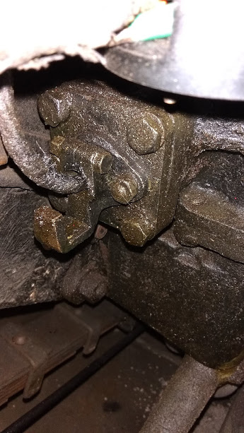
If my logic is working, the only way to prevent all parts from rotating is to have the long tube index into something that is stationary. I have fished around inside the steering post, and there is something in there …so that is good. I would suppose that the 2 grooves on the tube must match up with whatever is in the steering column. I have plenty of cleaning to do and will attempt to install it later.
I can’t remember, does the locating spiggot get formed inwards between the two slots in your photo. Once you have managed to thread the cable down the column (perhaps with the aid of a long semi-rigid pilot wire.) then you should be able to rotate and push the manette tube into the column and feel when it mates correctly with lower anchored tube.
Thank you for the great information. After 2 hours I did get the bottom disc to move. I will do some cleaning and oiling, then work on the installation a little later.
As I recall, the upper or rear tube slides over the forward tube.
That’s the way it is on Mark V and XK120 anyway.
You want to be aware that the wiring passes over a sharp edge of the forward tube here and, with moving the wheel in and out, can get chafed until it grounds out inside there. It happened on my 120, it would blow fuses every time I signaled a left turn.