New Torsion Bar Install 2022

I have replaced my original TBs with a set from XKs. They are STD thickness. I have also replaced the bushings and will essentially have a fresh front suspension. I have made the setting gauge to spec per the book, read multiple previous posts, and put it all back together, set it down and drove it about 100 miles.

The ride height, as measured from the lower control arm to the ground is 10 inches. The Complete Official Jaguar “E”, Bentley 2nd revision, page 248, Fig 12 shows the correct height should be 8 3/4". (+/- 1/4"). Quick math says I need to lower by 1 1/4" both sides. ( I guess I got lucky and both sides were the same height, and off by the same amount.

On the old forum I picked up the following: 24 splines in the front 25 in the back. 1 spline equals 3mm. Adjust the passenger side CCW to lower, adjust the Driver side CW to lower. I need 10 splines for 30 mm or just under 1 1/4". I chose to go to eleven splines.

My initial logic led me to believe that if you have the setting gauge in place, it shouldn’t matter what position the TB is in…silly me. So I got it “close” so the rear adjuster holes were just about aligned with the reaction plate and put it all together, using a bit of “force”…only to have the ride height too high as mentioned above.

Checking previous members’ posts, the key I think is my misunderstanding of the significance of the difference between the front and back splines…in that they are different.

Now I am debating on the best way to proceed. Two options:

  1. Start over with the understanding that, with the setting gauge in place, find the sweet spot on the TB where the front splines are engaged, and the rear adjuster bolt holes are PERFECTLY aligned all the way through the reaction plate.

This is accomplished by rotating the front splines, 1 at a time, inserting… by hand… the front about a 1/4" or so and checking the rear adjuster holes for PERFECT alignment.

Once this sweet spot is found, push the front splines all the way in. This is accomplished by removing the setting gauge thereby allowing the lower control arm to rotate a bit, perhaps giving a better axial alignment for the use of persuasion. Once the front splines are in place, rotate the LCA back in order to reset the gauge and then slide the rear adjuster back in place…and the bolt holes should be PERFECTLY aligned.

OR

  1. Since I know I am off…high… by about 10-11 splines, rotate the bar and reinstall. The problem here is that now the holes don’t PERFECTLY align. Close, but the bolts will not go through without persuasion.

As I type this out I think option 1…start over and put it all back together once I find the PERFECT alignment.

As always, I appreciate any feedback (am I on the right track?)
and/or your vote for option 1 or 2

Semper Fi,

Dave
I’d vote for option three, change your setting link by the amount you want, and then redo the trim bar setting. Less error this way.

This thread should have a subtitle…

“Ask @Erica_Moss!”

I have never used a spline counting method. I have no idea how to even attempt such a thing. It seems like witchcraft. If such a thing were possible it only seems like it could be arrived at for a specific manufacturer’s part, and even then could be subject to change depending on how consistent the steel is. Ultimately it would probably only apply to the specific set of bars that the test was conducted on.

I use the book method only of using a setting link and adjusting that link based upon what direction I need the car to go. Therefore rather than using a rigid link, I use a large turnbuckle as many here do, and I measure the span very carefully. If you measured carefully and used the book’s standard span and it left you high, then you know which direction you need to adjust the span. It needs to be shorter. It’s likely going to be 1/16-1/8" shorter to land you level.

But what shocks me is that the standard span resulted in you being high. The standard span was based on using tall skinny bias ply tires. Modern tires tend to leave me low with the standard span, and standard bars. Currently there are thicker bars on mine so the setting link is about an inch below standard length.

Also, if you’re running modern tires, take the book ground height figure with a grain of salt. You simply want the car level.

edit: I must also caution you that the setting link method is only accurate if you keep rotating the bar until both bolt holes line up exactly so that they both just slip right in. If you end up using force to get them into the holes, then you are overriding the setting link and by the time you bolt it together, the span will be slightly different than what you initially hoped it would be. “Slightly different” here makes a noticeable difference in road height.

3 Likes

Seems to me you should first read the manual as many times as required to fully understand the torsion bar setting process. It appears you are not fully appreciating the vernier effect that is afforded you by the differing spline count on each end of the bar.

Moving the bars by 10-11 splines at only one end of the bar as it appears is your plan will have a HUGE effect, likely putting the frame on the ground.

The 3mm for 1 spline you quoted was probably meant to mean 1 front spline CW, 1 rear spline CCW yields a 3mm change.

What you need to do is something like rotate the front of the bar by some number of splines, then rotate the “ear” at the back by some number plus one in the opposite direction and install the bar.

Or better yet, just follow Erica’s advice.

2 Likes

I would add one further note that if you did not loosen all the bushing mounts on the control arms/wishbones while doing this (as specified in the manual), and then only tighten them once the car was properly settled on it’s suspension, a significant part of your over-high ride height may be attributable to the fact that you are using your rubber bushings as torsion springs and they will probably need replacing in another 100 miles.

2 Likes

I recently put the front end in a friend’s 62 coupe. It’s still on the hoist. He knows not to tighten anything until it’s weighted normally on it’s wheels.

Have you properly measured the diameter of both the “old” TB and the “new” TB to ensure they are of the same.

I also made a gage for setting my adjustable link so I know it’s exact measurements along with some tapered pins that just slide in for initial setting
When it’s all lined up no force is required for any off it
Super Clean splines and anti siege
I’ll also lower the a-arm to almost vertical to unload the TB completely
I think the factory setting is a starting point for various reasons Ymmv
Don’t let the tb hit you in the head when it falls out if your working on your back
Cheers

1 Like

Fit a Rob Beere adjustable torsion bar reaction plate (sourced from UK). I believe Moss also has a similar adjustable reaction plate. Makes the job a lot easier. Rob Beere-Suspension

Like a grape you have to struggle to be great ….
I’ve sure thought about it

This as actually not a bad idea.

You will eventually be able to get your front ride height correct by a process of successive approximation simply by varying the length of your setting links, however in your case an adjustable tie plate will get you where you want faster.

Your thoughts on spline counting, bolt hole alignment etc are just confusing you. The point of the different spline count is to make the bar very finely adjustable; it’s essentially a vernier.

All you need to do to drop the front is to make your setting link shorter. It’s probably possible to calculate the right amount trigonometrically knowing your current ride height and desired ride height but maths is not my forte.

Thank you for the replies. I should have initially declared that the car is a 1970 SII.

I will measure, and compare the thickness of the bars in the next few days.

Thanks for your time today Harvey.

Thanks for your different perspective Erica, Harvey mentioned the turnbuckle method as well.

The lower control arm nuts have been loosened to allow the bushings some relief once I set the car back down.

I have read the manual many times, and hopefully this will prevent me from setting the car down on its frame. I am confident I understand the vernier effect.

I will try the setting link method and look for the holes to line up perfectly and then go from there.

1 Like

Trying to get the bolt holes to line up is the wrong sequence. Bolt the rear ears to the reaction plate first, then get the splines to line up perfectly using the setting link.

1 Like

Measure twice, adjust once.

From January 2020: As the car sits now decide how much you want to raise or lower each side of the front.

Disassemble per manual until you get to the point where the torsion bar is still in but unloaded. (UBJ, outer tie rod ball, & shock disconnected)

Using the shock mounts upper and lower measure the current length of the " setting link"

Add (or subtract) 0.75 times the amount you want to raise the car ( or lower) to find the new setting link length

1 Like

While this is just my opinion, and has had very little real time testing, I had an adjustable bar installed for some months. I had a couple of negative observations. First, in order to make the adjustments stress free, the suspension needed to be split, which is the hardest part of the job when adjusting the normal way. I watched someone adjust it without splitting it, but the car needed to be up on a lift and he threw all his weight into a long breaker bar. I couldn’t do that with the car on stands. The beaker bar would hit the ground before the adjuster actually rotated.

Next, there are fewer options on the adjuster than you have using the vernier ability of the bar splines, so the options at hand are pretty course and limited.

Next and in my mind worst, the strength of the original design is that you have a very thick reaction plate, and a very thick splined knuckle, sandwiching a much thinner frame ear, whose limiting factor is the joint where it’s brazed to the tube. When sprung all of the force is directed towards the center mass of the huge solid reaction plate. Even if the plate was not fully dead tight to the car, the worst you’d experience is a clunk. Nothing could actually ever fail dramatically. Even if the ear fully ripped loose from the engine frame, the car will probably still be left standing.

The adjustable plate takes the sandwich apart and pivots the knuckle inward by over 45 degrees so now the force vector isn’t pushing against the mass of the plate. It’s pushing the plate down and trying to rotate it. Fully laden you can visibly see that the plate will be canted forward slightly instead of being perfectly vertical as it normally is. It doesn’t matter how much you tighten the mounting bolts, it shifts the forces a lot and puts a lot more strain on the frame ear. There has never been a failure with these that I know of, but I felt it added an element of risk with very little reward and went back to factory.

3 Likes

A follow up comment to @69coupe Tom.
I looked at a lower control arm that I have out for plating. (S1 arm, if that makes a difference?) There indeed does seem to be about a .75 ratio between the hole for the lower shock mount and the end of the arm where the ball joint attachs. And since the torsion bar end is a zero vertical displacement pivot point, it does seem correct to adjust the change in setting length by this factor. Looking at it another way, a change in the setting length dimension of 1 unit is going to change the ride height by 1/.75 = 1.33 units. So Dave should consider this when doing his planning.

2 Likes

Yes I do feel the need to restate the obvious because that’s my job.

The 0.75 ratio between the setting link and front trim height assumes that you are following the factory shop manual. And that you are consistent in the way that you follow it. I would recommend an adjustable setting length.

Another possible source of error is settling that some people have found. I don’t have direct evidence of settling. But I believe it is possible even likely given the multiple components and load paths in the system. Especially likely on a full disassembly and reassembly.

I do like the above idea of jacking up the car on the center line at one end, to separate the front from the rear.

The new TBs are thicker by 2mm. Originals are 20mm, new ones are 22mm. I purchased these years ago and assumed they were original type TBs…that were of the same thickness.

Using an adjustable turnbuckle type setting gauge, I subtracted the difference (in my case too high by 1.75 Inches)…using the .75 ratio as mentioned…to come up with a 1.31inch difference.

1 Like

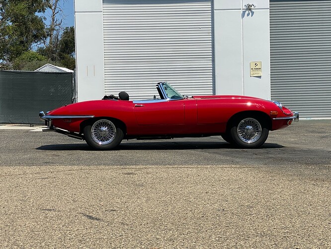
Here is the “after” picture.

I was happy to discover that once the steering tie rods and the UBJs were apart again, and I was down to removing the TBs and hunting for the proper spline combination front and rear, the bars came out readily. I was able to find a front/rear spline combination that will provide the adjusting rear bracket holes to perfectly line up. This is a job which will make you feel really happy when its completed…like most of the DIYs on these machines!

6 Likes