My IR thermometer measures about 165F to 180F on the radiator near the otter switch and on a black dot painted near the temp sender. the fans come on at about 175 and off at about 165. However the temp gauge is in the red at 165F.
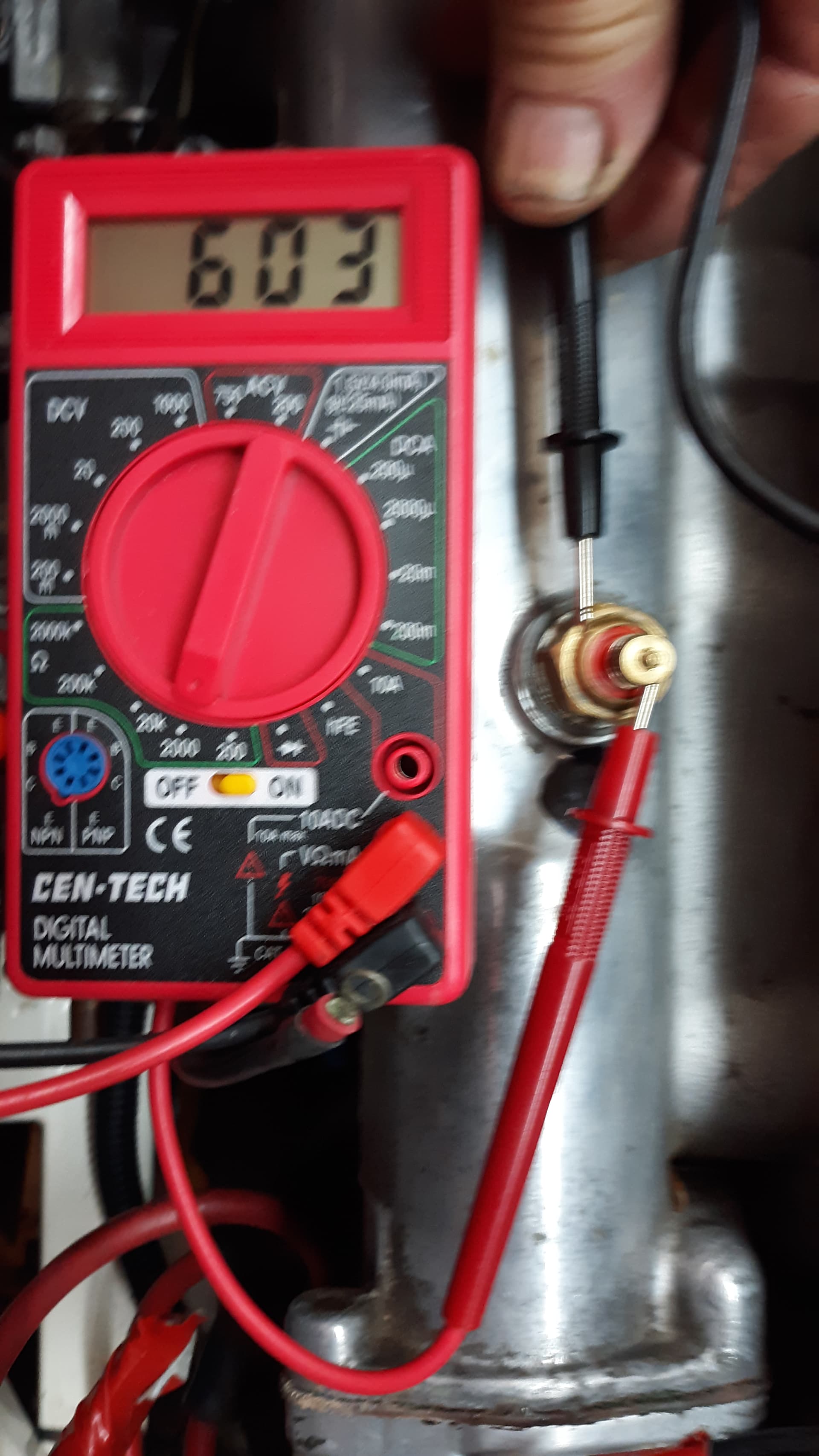
The sender measures between 950 ohms and 600 ohms at 60F on several different tries. At 175F it is 31 ohms. What should the numbers be? I have one reply that it should be:
30C-330ohms
70C-70ohms
110C-11 ohms
I can’t find any tests in the factory manual but have read there is a voltage regulator that could be the problem, How is this best tested?
It appears the PO replaced all the smith gauges with new or at least rebuilt Smith gauges and the sender is new.
The instrument voltage regulator is attached to the back of the fold down instrument panel. It supplies 10V to the fuel and temp gauges. If it wasn’t behaving, the fuel gauge would also be reading high. But you can test directly by measuring the voltage supply at the gauge. Some electronic meters have a problem reading the IVR’s output, though.
Rather than second guess my water guage, and nervously firing my IR reader all over I’d like to be the persnickety type that gets an absolute reading from the sender, straight from the source.
I had a similar issue in my 69 FHC. I started with the temp sender… inexpensive and fairly easy to replace. Make sure you get the crush washer with the new one. When that didn’t make the temp needle go back to where it had registered (for years!) O-R, I bit the bullet and put in a new CoolCat radiator and fans. All good now. I then put in CC’s electronic voltage regulator as well, because that was just more old stuff in that car that could go at any tiime. Didn’t that that complication for fuel and temperature.
Now that my car is on the road again I need to address the still ongoing problem of a maxed out temp gauge: IR readings near the sender are about 80 to 90C after a five mile run.
A heat sensor mounted on a intake manifold stud reads about 100 to 110C (fans come on at about 65C).
I have tried two different new senders, two different new instrument voltage regulators (both put out 10 volts), swapped the wiring to the fuel gauge (fuel gauge also went slowly to the max but seems accurate when reading the tank fuel level)
My voltage gauge is mostly in the On Charge area, about 15 V.
What can I try next? Is there a way to put something in the line to adjust the resistance output of the sender?
Also my engine got a new oil pump when it was completely rebuilt so I expect the oil gauge is reading low also at only about 30 lbs oil pressure.
As it happens, my sender is toast, so I’m about to figure this out. I have an NOS Smiths sender, unfortunately with different screw threads. But it’s good enough to give measurements. I did this with my lab setup, so more accurate than you could do on a car:
The response is non-linear, so you would expect some “crowding” as the gauge reaches the high end. I would imagine that the gauge compensates for this in some way. Because of the non-linearity, you probably can’t fix a bad sender with a resistor, which would simply add a linear load at all temperatures. If you want to give it a try, it couldn’t hurt to experiment with a 30 ohm resistor and see how it affects calibration.
I’m getting a couple of senders from a couple of non-“authentic” sources: Beck-Arnley and SMP. We’ll see if the generics are more accurate than the formal reproductions.
I have the same problem with a rebuilt and calibrated water gauge (White Post) and a new SNG sending unit. I also have a new SS IVR that puts out exactly 10VDC. I installed a mechanical gauge for comparison and found a spot on the engine that matches with an IR thermometer. See below. My Smiths gauge is reading about 25°C high. I plan to attempt a correction with a trimmer pot to set the indicated Smith’s temp to be what I read on the IR thermometer at the indicated location.
If you look at the drawing in John’s link, you’ll see that the gauge is linear, but the corresponding temps are an uncompensated projection of the sensor curve. Notice how the graduations are closer together at the right of the scale. So the hotter the engine gets, the less the needle moves. Good to know. Hopefully John doesn’t object if I link his drawing.:
A rheostat is really overkill, since you’ll set it once and never again. what you need to do is to measure the resistance of the sender @75c, and add enough fixed resistance to get to about 100 ohms total. That will cause the sensor curve to shift to the right, and may produce a result good enough for government work. Or wait a week or so, and I’ll report back on the Beck Arnley and SMP senders, so you can make an informed decision.
Not a bit, feel free. And note that I was doing this by eyeball, so given the width of the needle the exact temperature locations are just very close approximations; maybe ± 1F or 2F of where I show them in the drawing.
Thanks. Your diagram saved me the trouble of dissecting a gauge to figure out how they flattened the thermistor curve. They didn’t! The non linearity of the sender is reflected in the gauge. Notice how the slashes crowd together at the right end of the scale? The hotter the car gets, the less information is conveyed. The slashes may as well be labeled “hot” “really hot” “boiling” “melting” “incandescent” and “gone solar”.
I’d noticed that but never gave much thought as to the why. I was just happy to verify the needle at “L” (I’ve never seen it above between “M” and “A” though) wouldn’t result in immediate engine destruction.
Hello Michael, I read and followed your suggestions made in another topic about checking battery voltage against VR voltage to see if there is much difference as they should be nearly the same. What I found is my battery voltage is 18.6 to 19.1 and my VR voltage is 18.4. My voltage at the IVR is 18.4 going in and 14.4 coming out to the temp gauge. This test was with the car not running.
I checked this IVR voltage months ago and it was 14V and 10V.
Has something gone wrong with my battery to cause my temp gauge problems? I thought batteries should be about 14V only. I have had it on a high quality trickle charger most of the time. How should I manage a battery that is often just sitting unused?
Disconnect the battery before testing the voltage. There’s no physical way a lead/acid battery with 6 cells can put out that voltage. If it still shows very high voltage, then something is wrong with your meter would be my guess
Scott, my first guess is your voltmeter is not reading properly. I would first check the battery on your daily driver with this volt meter, engine off, and see what reading you have. 18-19v is clearly too high. If your meter checks okay on the daily driver, then there does appear to be a battery issue. You say the engine is off, I am assuming your trickle charger is also off???
A typical charged battery at rest is 12.6 volts.
Tom
(You also posted this in the Voltage Regulator thread, I am providing my same response here also)
Your battery is NOT producing 19v. If you are really reading 19V, your ALTERNATOR is generating that voltage, and the problem is the VR. Replace it and things should start falling in line.
Could I ask you consolidate your questions to one thread? I think you’ve spread this conversation out over at least three threads.
Sorry I have mingled electrical and temperature issues up somewhat but will try to post to the most recent and specific thread from now on.
I looked at the back of the temp gauge and could not find the adjustment “port” or gummed over hole some have mentioned having; perhaps only on earlier cars? I am thinking of getting another reliable source of info on the coolant temp besides a hand held IR thermometer; such as a mechanical temp gauge (at least until the original can be sorted out). The heat sensor I installed reads intake manifold temp at the stud in the head which seems to always be 25-30% higher than coolant temp. What temps would be considered getting too high for coolant temp and for head temps? I have evans coolant so expect the temps will be a bit higher for that reason but do not want to damage a good running engine by over heating the oil, for instance, by not having accurate info. My radiator is original but was rodded out by a good shop before re installing. All the hoses are new and the water pump. fans original too but seem to work well.